New Throttle / controller hookup question

Jonny333 said:
You mean double check it’s still 4.09v?

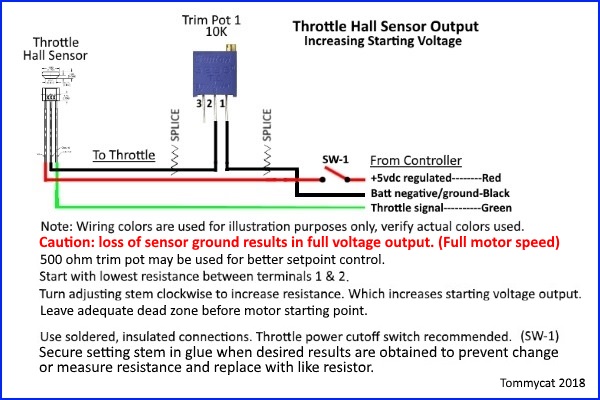
Was thinking if you have a bad hall throttle sensor or shorting strand of wire or poor connection, perhaps it's dragging the voltage down. Could just be a poor controller voltage regulator. This would require disconnecting the input power to the throttle and rechecking. E-brake still disconnected? (the only other thing that's using the 5vdc regulated power)

It seems to not exceed 4.09v. Would a new controller be the answer?

This may very well be your opportunity to get that controller with the e-lock feature... :wink:
 
The controller appears to be pumping out 4.73 V on the throttle powerline when I physically disconnect them from the throttle. I left the yellow LED voltage line and green signal line connected. I have an extension soldered to the throttle break wires, but it’s not connected.
I connected the Controller’s 5 V power line directly to the controllers signal line, with the throttle lines cut. The voltage output on the motor wires with wheel turning in the air jumped to about 11.85 V. Under this load, the controller power\signal line reads about 4.65 V.
The battery itself reads about 12.5 V.
I partially disassembled the throttle, Not sure what to look for. Wires and joints look OK. The three throttle wires are next to the magnet you mentioned. Looks to lineup and slide the full length with no excess either end.
 
I know a hall sensor throttle will drop the input voltage a bit when connected. Depends on how good the regulated 5vdc supply is... And the maximum output will be ~.7vdc less than the input due to the electronics. So where to go from here?

Check the DC milliamp draw of the throttle sensor. Putting your multimeter in series with the sensor supply it should be ~ 6.5mA. To test further you could try an auxiliary power supply for the throttle. Say by using just regular house hold 4 - 1.5vdc batteries in series would produce 6 vdc. (Hall sensors of that type are rated at max 6.5 vdc.) Positive to the throttle sensor power in. (red) Leaving the controller power disconnected. Negative to the blacks of both controller and throttle tied together. With the green connected as usual. And try it like that. Check at what power input (vdc) to the controller from the throttle is sufficient for maximum motor power and write that value down. Depending on if it's good enough, I see four ways to go...

1) Use it like that and change the batteries every so often. :?
2) Use a 6 volt Zener diode and tap off a voltage supply for it/ better regulator install/buck transformer. (provide better supply input).
3) Use a potentiometer type throttle which would not drop the input voltage and output the maximum same as the input.
4) If all checks are good, try the better controller and hope it's 5vdc regulated output is up to the task. :roll:
 
Ok, I’m afraid I’m getting lost here.
I took the throttle mechanism apart, and tried moving the magnet around to the best position and it was exactly the same as when assembled, hitting about 9 V motor output. I then put the sensor around an unrelated magnet I have on one of my tools, with the exact same results.
This all gets very tricky considering the conditions/tools I’m working with, I’m lucky I haven’t shorted anything out yet.
When I test the green sensor signal wire at rest it’s 0.865v. At full throttle, I get 3.3v. The red power line at rest gives 4.1v. 4.02v at full throttle.
I’m testing the wires at the point just before they enter into the hall sensor tiny black chip thing next to the magnet.

Regarding 6v test, I Used a 6v dc wall wort plug. It’s ok? It appeared to supply about 6.7v to the red throttle power line.
Also, you said:
“Check at what power input (vdc) to the controller from the throttle is sufficient for maximum motor power and write that value down.”
You mean to put a voltmeter simultaneously on the green signal wire, whilst pumping in 6v, and ttwisting throttle?
I did this and at about 3.7v on green signal I was getting what appeared as full power (motor wires read close to 12v output). After the dead band was past, I did not have to twist the throttle very much before it appeared to hit full output. I’m unable to drive it like this of course as everything’s apart, but I did put some load on the tire with my foot and it appears to have at least some torque. It’s providing much more power than the 9 V for sure.

Just to add: these readings may not be perfect. I’m holding things with my feet my hands and my mouth, and the tolerances are very close to shorting things out. Well you get the picture, LOL. I did try to measure everything at least twice.
 
Yes, that’s what I mean above. I be ripped it all apart, the tiny black sensor has 3 leads out of it. I put my voltmeter’s ground on black, and + on red, this reads 4.1v. Switch + to green wire leaf and it reads 0.865v. There is nowhere else to test! Should I upload a video to show what I mean?
 
No, I follow you. But what I'm looking for is the Amperage draw of the throttle hall sensor. Which will be in the milli-amp range.

TommyCat said:
Check the DC milliamp draw of the throttle sensor. Putting your multimeter in series with the sensor supply it should be ~ 6.5mA.

With the range set on DC amps. Positive meter lead in the amps jack (400mA) Between the controllers power output (5vdc) and the sensors power input. (red wire)
 
Ok, I got it, I misread that as mV. The mA reads 5.9ma at rest on the throttle sensor signal green wire, whilst hooked up to standard controller power feeds. The red power line next to it reads 9.16ma.

Since the previous test showed what appeared near full power at boosted 6+v input, would the best fix be to solder in a 6v stepup component of some kind on that red wire near the controller? Or a 6v step down from the main 12v supply?
If this is the case, I may have the components on hand to do it. I’ve got quite a few junked computer, RC, and other electrical components around. I’ve got a couple of 5 V to 12 V step up USB adapters I’m not using. I don’t suppose they would work in reverse? Or an old RC ESC that has s built in 12v->5v stepdown (for receivers,servos,etc).
Would the second best answer be to order the other controller with lock etc, and hope it supplies enough red line voltage?
Do the above tests clear the throttle as the culprit?
Thanks again tommycat
 
Jonny333 said:
The red power line next to it reads 9.16ma.

Do the above tests clear the throttle as the culprit?

I was ready to call it bad if you where over 10mA... close, but not knowing your exact testing procedures or equipment. I'm inclined to call it good. (These are very low amperage circuits which is why you need great wiring and connections!)

To recap from what I read...
If you can get 3.7vdc at the sensor input line of the controller... you get full power.
Since the hall sensor drops .7 vdc during normal operation, you need ~ 4.5vdc supply at WOT for full power.

Using your controllers output voltage may I recommend you try getting rid of the starting dead band first, as I know this drops the current use a bit. Which may help to lower the voltage drop...

wfGeHkI.jpg


For plotted charts and more details see https://electricbike.com/forum/foru...r-throttle-operation-testing-and-modification

Other wise use what power source you see fit to get to 3.7vdc output! (don't go over 6.5vdc, the closer to 5vdc and holding, the better.) :)
 
Thanks again Tommycat. I’m currently scouring over my old electronics to see if I can find a suitable trim pot. I found a few, but not sure if they have the correct specifications for this application.
I’ll order these as well:
https://www.amazon.co.jp/SODIAL-R-五つ-3296W-103-100Kトリムポット、ポテンショメーター/dp/B00SSLSYP6/ref=mp_s_a_1_3?ie=UTF8&qid=1548493077&sr=8-3&pi=AC_SX236_SY340_QL65&keywords=trim+pot&dpPl=1&dpID=41z240CgzrL&ref=plSrch
 
Handy little things those mini trim pots! Sure beats swapping resistors trying to find just the right one.

Glad to help along with what I can. And learn some too. :) But I would probably still rig up the battery supply workaround and get the scooter running under load (actual use) to see if it really works as desired before getting to deep into auxiliary supplies, ETC... :wink:
 
Well I have some bad news. I got it all soldered up with the 12v->5v stepdown and put back together for a test run. While more power than before, it’s still much weaker than the original setup. It almost can’t move with me on it, where as it would zip off before.
Any ideas?
 
:( Rats!
Verify all input/output throttle voltages? 5vdc in, above 3.7vdc output at WOT? Grounds tied together? Voltage at motor? Amp draw? Fully charged battery?
 
This may sound dumb, but hey, sometimes it's the dumbest things that stump us. First, it is definitely a 12v controller, not 24v? Also, many basic controllers have a connector labeled REV. Usually. When this is shorted, the motor runs in reverse at 1/2 speed max. If there is a REV connector, does it have a link in it?
 
Aussierider, No rev feature on this one. It’s clearly labeled 12v, but I know 24v is a much more common option, and given chinese QC anything is possible.
Tommycat, 3 ground wires soldered together, motor wires about 11.7v, about 9.8amps, battery 12.7, I’ll take throttle apart again to recheck voltages. Ok, 4.26v wot on green signal wires exiting HAL. Exactly clean consistent 5.0v entering Hal on red wire.
Btw, generally speaking, in circuits bearing some amps (ie battery wires), does the negative wire need to be as thick and robust as the positive?
Also, what’s your take on these brushless ebike testers? Would they help on this brushed setup? I’m thinking of getting one anyway to help on a new broken brushless scooter I recently bought:
New 24V/36V/48V/60V Electro Car E-bike Scooter Brushless Motor Controller Tester
https://s.click.aliexpress.com/e/cCEIC9lm
 
Jonny333 said:
9.8amps... :(

4.26v wot on green signal wires exiting HAL. Exactly clean consistent 5.0v entering Hal on red wire. :thumb:

Btw, generally speaking, in circuits bearing some amps (ie battery wires), does the negative wire need to be as thick and robust as the positive?

Yes it does. It needs to be able to return current just as well as the supply side.

Also, what’s your take on these brushless ebike testers?

Sorry, no experience with one. Though they look handy to have.
 
So what’s your take at this point? The throttle is clear? That only leaves the controller. I could order that alternate controller, and if that is also a bust I’ll just put the original system it came with back together.
Given these 12v systems are much harder to find than the 24v+ ones, is it possible they just slapped a 12v label on a 24v/36v/etc. set? If so, is this how it would behave?
Something I’m not really clear about is compatibility. Both the new controllers available are rated at 250 W, yet my motor is rated at 170 W or something.
Also, is there some kind of safety cap in the controller that is causing this low power output? Or are all these cheap chinese controllers just really bad quality And we’re doomed from the start?
 
I can't figure how it could work well with throttle output of 3.7 vdc and not now? Does jumping the supply and output on the throttle again with the new supply, change the controller output/power for the better?

If you could post some good pictures of the controller's interior and components, perhaps that could shed some light?

When you where testing the old controller set up. What motor amp draw (and voltage) did you get when it was running well?

If a controller is rated at 250watt output with 12vdc in that should put out over 20 amps. :? But a motor can be over-volted and higher amperage till it can't shed the heat... are the brushes good?
 
Yes, the throttle seems ok. It now has deadband on both ends (top band wot).
Motor seems totally fine. Got a bit warm after half an hour of continual use on the original set up. It’s never gotten a chance to get warm since installing the new throttle and controller, It’s all way too weak.
It seems like the controller is the bottleneck. Is there a specific component in the controller that controls how much 12 V current is allowed to pass through it to get to the motor?
I didn’t measure the original controller values. I could tell it was maxing everything out (a good thing for our purposes). It seemed simular to hooking the battery directly to the motor leads (which I tried).
I’ll post a video later of the controller if it’s helpful.
 
Jonny333 said:
Is there a specific component in the controller that controls how much 12 V current is allowed to pass through it to get to the motor?

I’ll post a video later of the controller if it’s helpful.

From what I've read a brushed controller can use several different combinations of control to vary the amount of output.
From a simple power transistor setup, to a pulse width modulation circuit, and combinations of both. All above my experience but for others of the forum internal pics may get a response.
 
Here’s a video of the issue with a closeup of the controller disassembled:

https://www.youtube.com/watch?v=5qK8YiH_tbc&feature=youtu.be


Just to add, the old controller and mod is right at the beginning of this video:
https://www.youtube.com/edit?o=U&ar=2&video_id=RV3zsVRA6YE

I’m wondering if I could fix this new problem the same way I did the old one. Just remove the component in the new controller that’s limiting the amount of power it lets through. I realize this risks burning the motor out in warmer weather, but I really don’t care, as it’s useless to us at these lower power levels anyways. Besides, it would be a good excuse to upgrade the entire system, LOL. Just to recap, the old system went from like 6 V to full voltage by removing that ceramic shunt thing That would heat up. Which piece would I cut out on this new board? The two chips I pointed out with thermal paste, they were screwed onto the side of the controller case, obviously for cooling. Would those be the two pieces to remove?
 
Some screen shots...


VxCqP9g.jpg


WQ58ttZ.jpg


mBtdJLl.png


The most interesting thing I saw was the sticker on the controller case... Why would you have two power choices at the same 250 watts? :shock:
 
Thanks for posting the stills. I agree, the chinese standards leave a lot of room for mischief.
 
Could it be possible that this controller is for a potentiometer type throttle only? If you got your pot(s) in, why not wire one up and see how it works?
 
Back
Top