Newbie question - motors and 9 pin

Stevew77

1 mW
Joined
Jun 25, 2019
Messages
11
Hi,

Im totally new to ebikes, have an electrical background and was hoping people way more knowlegable than me could answer a few basic questions on motors and plugs. I thought when i got this motor with a weird plug "uh oh...."

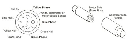
Ok... I bought a 250W unbranded hub motor that has a 9 pin julet plug. Does anyone have any diagrams on what pin does what please, and can i run them with any off the shelf controller?

Are hub motors with 9 pin connectors actually permenant magnet 3 phase motors driven by a DC-to-3 phase converter?

Are most hub motors 3 phase? I thought maybe they were PWM controlled dc motors?

That should do it for starters...any help much aprreciated. Great site by the way.
 
Welcome to the forum

These motors are 3 phase DC, but they don't work like a 3 phase AC motor. And while PWM is used for power management (speed control), it's not being used to imitate AC to run the motor. Instead each phase is fired off by a micro controller based on the stator's position. A BLDC motor is just a stepper motor who's controller is programmed for continuous rotation.

You should be able to run the motor off most BLDC ebike controllers, but the chances of being able to just plug in the connector are slim to none.

There is no standard for the positions of those 9 pins. The 3 thicker pins are the motor leads. the other 5 include a ground, a +5v, and 3 outputs from the hall sensors. Also of note, the wire color means nothing. While red and black usually do mean +5v and ground, never assume that's correct. So to make the controller work, you'll have to match the hall and phase wires with the controller without relying on the colors. there's a handy flow chart for doing this. it's easier than it sounds.


fetch
 
Hi

Thanks for the info, that sreally helpful.

What type of voltage wave form would the controller output on each phase? 3 phase usually means 3 voltage signals 120 degress apart in phase. Are there diagrams of this?

I havent worked with steppers before, but I'd have thought a "step" is a single DC "on/high" signal, but in this case it sounds like the volatge moves in a "wave" moving around the stator, to create rotation?

Sorry...new to all this....
 
There's a number of threads about various controlelr and powerstage designs; they'll probably explain in more detail than you want, how all of this works.

But for basics, you can just go to the Welcome Message to New Members thread, which contains links to various sticky index threads, that link to stuff like "how BLDC motors work", how batteries can be setup, etc.
https://endless-sphere.com/forums/viewtopic.php?t=82507
 
Stevew77 said:
What type of voltage wave form would the controller output on each phase? 3 phase usually means 3 voltage signals 120 degress apart in phase. Are there diagrams of this?

I havent worked with steppers before, but I'd have thought a "step" is a single DC "on/high" signal, but in this case it sounds like the volatge moves in a "wave" moving around the stator, to create rotation?

Sorry...new to all this....

AC moves in a wave like pattern exactly 120 degrees apart running at 60HZ (or 50HZ in the EU).

DC moves in a similar way, but at the speed of the motor's rotation, and not exactly 120 degrees apart at all times if measured by time. each pulse is sensed and fired individually as is needed (or guessed at, in the case of a sensorless BLDC).

There are also different ways that this can be handled. Sensored is what you have. it can also be sensed without the hall sensors, using the field effect of the phases and magnets themselves, or just guessed at by old and cheap style sensorless controllers.

The wave form used most often is "square wave", which is really a trapezoid. Newer more expensive controllers use true sine wave control, but there are still some advantages to square wave controllers.
 
This is the usual pin out for the 9 pin Julet connector,
Z910_Pinout.jpg

Most motors have the male pins coming out of the motor, so the connector will fit thru a 12mm axle nut, makes for easier maintenance. I've bought about a half dozen motorsthat use the above scheme, and the wires were as shown.

Any brushless controller should work. I have bought more than a few controllers, and they always worked if I just matched up the colors on the phase wires,and on the Hall sensor wires. Other users have encountered mismatched colors. I hope that is a thing of the past.
 
This is the usual pin out for the 9 pin Julet connector,

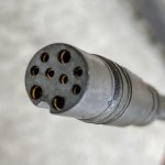
Mine is also 9 pin, but unfortunately it has a totally different configuration, physically.
(The large pins are at top and bottom.)

I think mine is the odd one out.

IMG-0346.jpg
 
I believe they call the connector I posted a Julet Z910. It's good for 500W, maybe a little more. Other connectors like the Z916 are used for bigger hubmotors. And maybe that's not good enough, so you have your connector.
 
This is the usual pin out for the 9 pin Julet connector,
View attachment 255643

Most motors have the male pins coming out of the motor, so the connector will fit thru a 12mm axle nut, makes for easier maintenance. I've bought about a half dozen motorsthat use the above scheme, and the wires were as shown.

Any brushless controller should work. I have bought more than a few controllers, and they always worked if I just matched up the colors on the phase wires,and on the Hall sensor wires. Other users have encountered mismatched colors. I hope that is a thing of the past.
HIya- re main Julet plug-The 'motor side male and controller side female' combo is sometimes reversed! Re the Airwheel. My Airwheel bike has the above combination, but the male and female connectors are reversed on the [older mode] Airwheel scooter [grrrrr]. But thanks for the above info which Ive been stewing on for a week. I guess we have to hold our breath and go with what seems to match eh!
 
Back
Top