Molten-Core
10 mW
- Joined
- May 22, 2018
- Messages
- 32
My friend Dimitris said "Knowledge is for everyone", so here is to him, to the people of this forum, to everybody that gave me the smallest of information, i will be sharing back my findings on this work.
I bought a few weeks ago a Niu N1S Civic at a fairly low price, it was a demo unit and partly damaged (scratches and plastic mainly), i tested it and it wasn't up to my expectations, i drive for a now a Honda CBF1000F, i don't need much top speed as i usually cruise at around 55km/h, i need the torque to get rid of anyone behind at the light and for evasive maneuvers (yeah, Brussels is a warzone), and given all the idiocy going around here they are planning to shift the whole city to 30km/h max, my days driving the CBF are numbered...
My goal from this work is to get better torque from this scooter, and i want people to be able to hear me when i want them to, so i may be integrating a soundbox along the way, i also want the scooter to stay reversible, if i ever change my mind i want to be able to unplug everything i added and put back the original hardware.
here are some pictures, they are clickable:

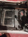
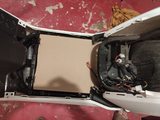

As you can see from this pictures the primary battery doesn't take much space, there is a lot of wasted space there, so i will be using all that space to house a 20s22P battery made with samsung 2900e that tumich sells at a very very affordable price, we are looking at almost 5kwh of energy storage with a 220 continuous amps.
I'm looking forward to working on this project, i'm waiting for batteries, nickel, dc dc converter and a 120amps breaker to arrive.


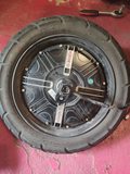
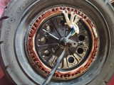
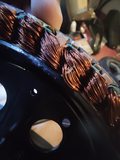
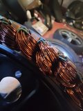
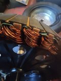
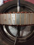
On these pictures you can see the specs of the bosh hub motor (60v, 1500w nominal, 2400 burst), the original controller, the new sabvoton 72150 controller, and how it will be positioned, it fits really snuggly right there, i drilled 3 holes to maintain it there.


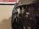
In the first picture you can see the connector going to the controller, and no matter where i look i cant find a place where i can buy a female counterpart alone, it's almost driving me nuts...
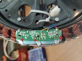
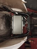
In the second picture you can see the integrated alarm, i think i'm gonna be replacing that with a keyless entry system, in the third picture you can see the DC DC converter that outputs both 12v and 5v, i think, but not quite sure though, that the 5v are only for the usb for phone charging, i will be replacing the converter to a more appropriate voltage source one, and i will probably be replacing the 5v part with a wireless charger for my phone.
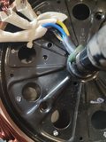
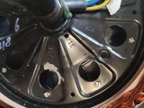
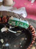
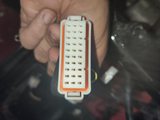
In the 3rd picture you can see hall wires, one of them is missing, it's actually the motor temperature wire, i think i will open the hub and see if i can add a temperature sensor, if i do so i will probably add some statorade.
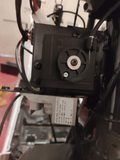
The last picture show the hall throttle, if i can get another one like that i will probably do a mod to have a reversible throttle, Brussels is a very hilly city with a lots of going up and down, having the possibility to control my regen brake would help a lot given that i do around a 100 to 150km a day.
I bought a few weeks ago a Niu N1S Civic at a fairly low price, it was a demo unit and partly damaged (scratches and plastic mainly), i tested it and it wasn't up to my expectations, i drive for a now a Honda CBF1000F, i don't need much top speed as i usually cruise at around 55km/h, i need the torque to get rid of anyone behind at the light and for evasive maneuvers (yeah, Brussels is a warzone), and given all the idiocy going around here they are planning to shift the whole city to 30km/h max, my days driving the CBF are numbered...
My goal from this work is to get better torque from this scooter, and i want people to be able to hear me when i want them to, so i may be integrating a soundbox along the way, i also want the scooter to stay reversible, if i ever change my mind i want to be able to unplug everything i added and put back the original hardware.
here are some pictures, they are clickable:


As you can see from this pictures the primary battery doesn't take much space, there is a lot of wasted space there, so i will be using all that space to house a 20s22P battery made with samsung 2900e that tumich sells at a very very affordable price, we are looking at almost 5kwh of energy storage with a 220 continuous amps.
I'm looking forward to working on this project, i'm waiting for batteries, nickel, dc dc converter and a 120amps breaker to arrive.


On these pictures you can see the specs of the bosh hub motor (60v, 1500w nominal, 2400 burst), the original controller, the new sabvoton 72150 controller, and how it will be positioned, it fits really snuggly right there, i drilled 3 holes to maintain it there.


In the first picture you can see the connector going to the controller, and no matter where i look i cant find a place where i can buy a female counterpart alone, it's almost driving me nuts...
In the second picture you can see the integrated alarm, i think i'm gonna be replacing that with a keyless entry system, in the third picture you can see the DC DC converter that outputs both 12v and 5v, i think, but not quite sure though, that the 5v are only for the usb for phone charging, i will be replacing the converter to a more appropriate voltage source one, and i will probably be replacing the 5v part with a wireless charger for my phone.
In the 3rd picture you can see hall wires, one of them is missing, it's actually the motor temperature wire, i think i will open the hub and see if i can add a temperature sensor, if i do so i will probably add some statorade.
The last picture show the hall throttle, if i can get another one like that i will probably do a mod to have a reversible throttle, Brussels is a very hilly city with a lots of going up and down, having the possibility to control my regen brake would help a lot given that i do around a 100 to 150km a day.