zerogee
1 W
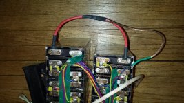
The pack ( https://endless-sphere.com/forums/viewtopic.php?f=14&t=64348) is split between C9 and C10. I thought things went well until I checked voltages after the split. Need help troubleshooting...

Pack was fully charged and not used since last fall. Before the split the pack was at 53.3V and individual cells resting voltages measured on each cell.
Prior to split.
C1 3.33
C2 3.33
C3 3.33
C4 3.34
C5 3.33
C6 3.34
C7 3.34
C8 3.33
C9 3.33
C10 3.33
C11 3.33
C12 3.32
C13 3.33
C14 3.33
C15 3.33
C16 3.33
This is why I thought cells were well balanced.
After split during charging.
C1 3.48
C2 3.57
C3 3.68
C4 3.70
C5 3.47
C6 3.79
C7 3.79
C8 3.44
C9 3.59
C10 3.50
C11 3.61
C12 3.42
C13 3.64
C14 3.50
C15 3.61
C16 3.51
Charger went from red to green in like 5 minutes then repeatedly turned on and off for maybe an hour (C6 and C7 hit 3.89V, C3 and C4 hit 3.79 during this period) then stayed green. Left it on for a few hours until bedtime. Not as well balanced as it first appeared.
After charging for a few hour.
C1 3.52
C2 3.57
C3 3.68
C4 3.70
C5 3.47
C6 3.79
C7 3.79
C8 3.44
C9 3.59
C10 3.50
C11 3.61
C12 3.42
C13 3.64
C14 3.50
C15 3.61
C16 3.51
Next day resting.
C1 3.51
C2 3.61
C3 3.68
C4 3.70
C5 3.51
C6 3.74
C7 3.74
C8 3.47
C9 3.61
C10 3.53
C11 3.64
C12 3.44
C13 3.66
C14 3.54
C15 3.65
C16 3.55
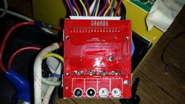
After the split I can't measure total pack voltage either on the pack or at the power port with the key on. However, individual cells resting voltage are still around 3.33V. I can measure cumulative voltages from C1 to C5 on the BMS then nothing after that. I measure cumulative voltage on the main pack from C1 to C5 then nothing between C6 to C9. I can also measure the cumulative pack voltage on the minor pack from C10 to C14 and nothing on C15 to C16. I can't measure voltage between the two packs on C9 to C10.
To make the split, I cut the battery tab in half after removing that sense wire then soldered my C9 to C10 wire to the tabs. I have continuity on the added wire between C9 and C10. I also have continuity on the sense wire between the sense wire extension and the splice on the center of the C9 to C10 wire.
I had power OFF. I covered all terminals with tape and only worked one wire at a time to prevent shorting. I unplugged the BMS prior to starting.
Any assistance is appreciated. Thanks


