Nuvinci developer kits for cheap

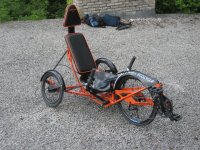
I couldn't resist one of these hubs to replace the 8 speed deraileur on my 4kw 80-100 powered Stinky :
http://endless-sphere.com/forums/viewtopic.php?f=28&t=12768

With the old setup, the chain and rear sprockets wore out quickly and then would often slip in the higher gears with too much load.
I am hoping the ability to use BMX chain and a 1/8th " wide sprocket with a straight drive line will sort this issue.


I plan to develop a gadget that will allow selection between Manual or Auto gear shifting this hub on the fly, (which you can select while riding).
The stock system seems to cater for either one or the other, because they each require different configuration files to be loaded into the shifting servo.

For Auto mode, the wheel speed signal would be passed to the servo as normal, and shifting would take place as defined by the shift tables.
For Manual mode, the wheel speed signal would be synthesized by a microprocessor (a re-programmed verion of the TA2 board), the apparent wheel speed could be controlled by a pair of up/down buttons on the handlebar, forceing the servo to change gear when you want to, just like a sequential gearbox control :)
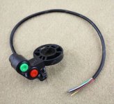
Up-Down gear selector switches.jpg

In Manual mode we could add refinements like:
1) Auto shift to low gear when stopped
2) An led display to show which gear is selected


All this stuff is a few weeks away, I am still trying to get some ideas straight. Tomorrows job is to have a go at laceing the hub into a wheel :?

Once I have this feature developed, I should be able to make it available to all who want it, meanwhile if you have any ideas for similar features you think might be useful, then I am all ears!

Burtie
 
I would only add a current-control mode, so that the autoshifting will occur not only for speed, but also shift down upon overcurrent.

Theoretically, wheel speed should drop if the controller itself has overcurrent protection in it, but if this device could monitor current it could be separately adjusted, while on-road, unlike the current limiting in a controller that requires USB programming. Useful for experimentation.

Additionally, it'd be nice if it could also monitor voltage sag, so that if it sags too far under load, it could shift down for that, too.

ATM I'm planning on using the CA to do the current-control mode, partly because it can be adjusted on-road. I haven't worked out any details yet, other than what's been discussed in this thread, as the bike isn't built yet. :(
 
Burtie said:
I plan to develop a gadget that will allow selection between Manual or Auto gear shifting this hub on the fly, (which you can select while riding).
The stock system seems to cater for either one or the other, because they each require different configuration files to be loaded into the shifting servo.

I was thinking the same thing. However I was planning on interfacing the to NuVinci controller's serial port. Looking in the appendix, it looks like you can send a command via serial to switch the controller from auto to manual. When in manual mode you can increment and decrement the 'gear position' by a few steps at a time. Also this gives you full access to the 10 auto shift tables which can be loaded.

I could also take the serial output from the CA, which would give me current measurements.

I don't have my NuVinci yet, so I don't have any details.
 
It is very simple to do.

The "Display" port is nothing more than a TTL level RS232. it outputs 4 lines to display. those are the 4 lines of information that their display panel shows. basically like a 4X20 VT100 terminal.

For control you need a Keypad with 3 ASCII keys. "1", "3" and "5". Pressing the "3" key will toggle between Manual and Automatic. In manual mode pressing the "1" will down and the "5" will shift up.

In Automatic mode pressing "1" will scroll down through the list of 5 shift maps. "5" will scroll up. the 4th line of the display will show the name of the shift map selected or "Manual"

The information on the "display" port is identical to what is on the USB port except that it is at TTL level.

so what is needed is simple. a PIC or AVR or Atmega based circuit hooked up to 3 keys and a 4X20 display, that can emulate a basic VT100 or similar RS232 terminal. that will work for the basics. Toss in a little more processing power and sensors and you can do what you need.

rick
 
I tested it using a TTL level RS232 to usb adapter and my PC. It does not even need the full VT100 emulation. i think it only uses a couple of the "esc" sequences. like "Home" and "Clear".

rick
 
Thanks for the detailed info rick.

Sounds like that may be the best way to get to the required features :)
 
So! Who is using this on a crazy high power bike! I'm hoping we can repeat the results I have seen by some of the gassers, claims of 9 HP before it just starts to slip with no real damage, just a slight darkening of the traction fluid.

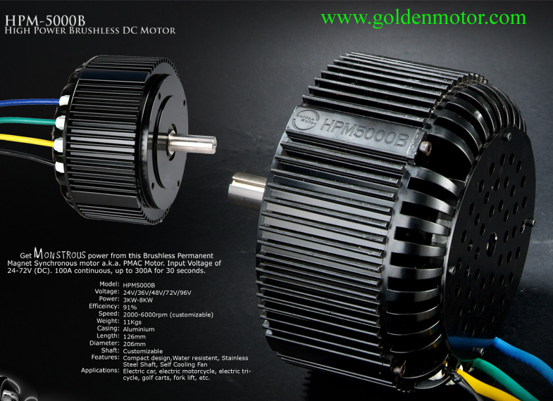
I'm gonna try this with a 3 - 4 Kw set-up for exhibition purposes in the near future if all goes as planned with either this GM:

http://www.goldenmotor.com/

HPM5000B-BLDC.jpg


Or a Colossus if I feel up to installing my own halls unless they are being made available that way?

I'm shooting for a bike that will be capable of about 70 MPH but only ridden to about 50 MPH to keep things robust and reliable (I can hope right? :lol: )

Well, anyhow, just wondered who else has put some high power into a NuVinci, and just by luck, the GM likes to run at 48V and 50A for 89% efficiency, so I am hoping this will work well with a nice jackshaft reduction that shouldn't have the hub spinning more than about 900 RPM of the 1000 RPM maximum recommended.

This isn't something that will happen any sooner than next spring unless I get some more business, who knows, have a bite for a amped bikes kit, and hopefully we will sell some of the mid-drives. :)
 
My general understanding of internally geared hubs is that in the 1:1 mode there is the best efficiency, or least friction losses inside the hub because there are no planetary gears in action.

Is the same true for the NuVinchi? Are the sphericals still spinning in 1:1 mode?
 
They are spinning regardless, as they are the link between the input-output rings, and 1:1 just means the sphere shafts are horizontal, thus the input ring and output ring are contacting the spheres at the same size diameter.

[youtube]kVPjhmTThPo[/youtube]

And as long as I am staying under 48 ft of torque 5KW sustained power, and less than 1000 RPM at the hub, I shouldn't have to worry about it slipping.

I'd think this would be a decent amount of power for a race bike like the recent one that PaulD won, with a rider as skilled as the man himself.

I'm all about racing, but I know I am not at that level of skill, so mine will be more of a exhibition bike, but still would be a ton of fun to race! :mrgreen:
 
A couple of things I want to share that I have discovered about these kits that may save someone some frustration. One thing is that the main power to the kits controller should be disconnected when you are sending the shift & configuration tables to the controller. If you don't disconnect the power, the controller will go into it's default settings called "Safe Mode"

Secondly, and I haven't confirmed this with anyone @ Nuvinci but it seems to be what was causing a problem I was having, is that if you have input at the Nuvinci hub (i.e. not freewheeling) and you are traveling faster than the maximum speed you have set in your configuration table, this will also cause the controller to go to "safe mode." What seems to happen in this case is that the Nuvinci tries to shift into a higher gear range than is allowable so it defaults to safe mode.

After about a week of playing around with the thing I finally have a shift table I'm happy with. I think I can still fine tune it, but overall I am pretty happy with what it is doing now.
 
StudEbiker said:
.

After about a week of playing around with the thing I finally have a shift table I'm happy with...


These things are quite fun to play with :)

I have been working a bit on my gadget to allow semi-auto shifting of the gears, using up/down buttons attached the handlebar:

http://www.youtube.com/watch?v=V2o-9B4oDT0
[youtube]V2o-9B4oDT0[/youtube]


:D
Burtie
 
So are you just interrupting the speed sensor, and sending the control unit a false speed to get the gear you want?
Then in fully automatic mode, you just send though the speed data un-modified?

Also, where did you get the push button from? (I would like one of those.)
 
ashwright said:
So are you just interrupting the speed sensor, and sending the control unit a false speed to get the gear you want?
Then in fully automatic mode, you just send though the speed data un-modified?

Also, where did you get the push button from? (I would like one of those.)


You've got it 8)
Cut off the inductive proximity sensor, use the red wire to supply 5v to your gadget.
Feed your synthesized TTL speed signal into the green wire, via a 180 ohm resistor.

Then work out how to re-use the speed sensor as an input to your gadget (have not done this bit yet), so you can choose to use the real wheel speed, or a synthhesized speed as the input to the Nuvinci controller.

http://www.ebay.co.uk/itm/320745512438?ssPageName=STRK:MEWNX:IT&_trksid=p3984.m1439.l2649
( you need to remove the latching mechanism on the red button )

Burtie
 
I couldn't tell for sure, but it looks like your synthesized signal is essentially doubling or halving the frequency from one "gear" to another.

If true, it would be simple enough to use a 555 or 4049 generating the root signal frequency, then dividing it with something like the 4520, to get up to 8 gears (by cascading the two 4-bit counters).

It'd require a multiposition switch (like a rotary) to pick the divided frequency, or an electronic switch with up/down control to select which input is active at the output. (I can't remember which chip does this, but I am pretty sure there's a 4000 series or 74x series that does it; if not Maxim probably makes one--they like up/down button controlled chips. :))

I probably already have those chips laying around, so I might try doing this.

Another option is a digipot with up/down control as the timing resistor in the freq generator, calculated out with the cap value so that step size on it becomes halving or doubling the frequency (if this is even possible; I don't know how to figure that out).


BTW, when you forget what chip does what, this site:
http://ganswijk.home.xs4all.nl/chipdir/
is pretty useful for just glancing thru lists of functions, or if you remember part of the number, but not the rest, etc.
 
amberwolf said:
I couldn't tell for sure, but it looks like your synthesized signal is essentially doubling or halving the frequency from one "gear" to another.

Its a little bit more complicated than that.
The 6 frequencies are chosen to mimic the speeds between where you want your auto gearbox to shift. This is done so that the Nuvinci can be operated in Auto or Manual mode, without changing the shift table.

For my 6 speed, 26" wheel with 45mph max, I ended up with frequencies like this:

5 hz
14 hz
21 hz
31 hz
41hz
50 hz

YMMV.

I guess you could generate the signals using discreet hardware, but a small uProcessor, it you want to use one, makes the job much easier.
 
Once again Burtie, you come up with some neat ideas.

My experience with my Nuvinci so far made tying to use in manual mode too difficult for me. But that was using a pot. I was too busy trying to concentrate on driving and watching the road in simulated race conditions that trying to get a precise shift spot based on amps and speed was not easy. I played with the automatic, and am much happier. It takes a LOT of testing to come up with a good shift table. Set the shift points wrong and it wont accelerate to the next step and you are essentially stuck in first gear, or it sets the gear too high, that you aren't getting much advantage out of it.

But once you get it right it is really cool to give full throttle and watch amps and speed. Your speed climbs faster than with a single gear, and your amps are lower as the motor is closer to max RPM. As it goes through the shift points your amps go up and down.

Are you planning on selling it once you have it ironed out?
 
Burtie said:
I guess you could generate the signals using discreet hardware, but a small uProcessor, it you want to use one, makes the job much easier.

If I had any programming skills, sure. :)

I do actually have a couple of STM MCUs, the STM8 in a USB stick, and the STM32 in the Circle, but they are programmed in C, IIRC, and I just haven't been able to learn it; I have never been good at that sort of thing (and math). It's not very intuitively graspable, which is all I am really any good at. :(

I'm sort of ok at sticking things together that already do what I need to do, but troubleshooting them when they dont' work as needed, that's beyond me most of the time. I found that when trying to learn the stuff to build up my idea of an ebike "safety computer", back when i first started my whole ebike project.

Since I also don't have money to pay someone to write the thing for me, or buy something that does it, alternate methods like the one I posted before, or one I am posting below, are my easiest way of replicating your idea. :)

Anyhow, I guess it's not quite as simple as just a clock divider, with discretes, but it should still be doable probably almsot as easy.

A 4017 decade counter, clocked and direction set by teh up/down switches as pressed, could be used to turn on switches in an analog switch chip, like the old 4066 quad. That chip would be wired up to switch resistors in and out of the timing circuit on the 555 or whatever, to generate the timing pulses to shift gears.
 
Hi I have got one of these kits that I'm thinking of using fir now with my 1200w cyclone. Then later I like use two cyclone motors. But for now what gear would you lot thinks best for one motor. I have a 20t freewheel or is this two small any help thank yous all
 
Idontwanttopedal said:
Hi I have got one of these kits that I'm thinking of using fir now with my 1200w cyclone. Then later I like use two cyclone motors. But for now what gear would you lot thinks best for one motor. I have a 20t freewheel or is this two small any help thank yous all

It depends on what size your chainring is, as well as your wheel diameter, usual terrain, and preferred cadence. The N171 hub has 0.5:1 underdrive and 1.75:1 overdrive If you use a 44t ring and a 20t freewheel, then the maximum overdrive ratio would be equivalent to 77/20. That's a 100 inch gear if you use a 26 inch wheel with a fat tire-- plenty high for pedal only, but maybe a little low for power assist if you don't want to spin fast. You'd have to spin the pedals a little over 100 rpm to get to 30mph with a 100 inch gear. If you don't have enough motor power plus pedal power to go that fast, then it's probably a pretty good ratio.

Another thing to keep in mind is that the N171 is pretty efficient at near direct drive ratios, but becomes more and more inefficient in extreme overdrive or underdrive gears. You might want your direct drive ratio to be close to an all-purpose gear ratio for that reason.

I set up my wife's power-assist NuVinci bike with a 45/18 primary gear, yielding a 116 inch top gear with the wheels and tires she's got. That will give her 31mph at 90rpm in top gear.

BUT BEFORE YOU MOUNT THE FREEWHEEL, note that you can only take it off using a special tool set, and that the special tool set only works for freewheels that have four-prong remover interfaces, like these:
shmxf2-1.jpg
417FF15C9FL.jpg


If you use a freewheel with a different remover interface (or no remover interface), it will be quite an ordeal to take it off later. Even if you use the right kind, it will be easier to change the chainring than to swap the freewheel, so be deliberate.

Chalo
 
The motor has a 14t sproket on it which go to a 48t on crank and then from a 48t to the hub with my old 8 speed set up it would pull upto 5 gear and do 45 mph with out pedaling
 
drewjet said:
It takes a LOT of testing to come up with a good shift table. Set the shift points wrong and it wont accelerate to the next step and you are essentially stuck in first gear, or it sets the gear too high, that you aren't getting much advantage out of it.

But once you get it right it is really cool to give full throttle and watch amps and speed. Your speed climbs faster than with a single gear, and your amps are lower as the motor is closer to max RPM. As it goes through the shift points your amps go up and down.

This is exactly what I'm dealing with right now drewjet. Can you offer any advice on how to get zeroed in on good settings?
 
It took lot of trial and error. And I could probably still fine tune some more yet. Tomorrow is my first time to use it in a race. That will be the ultimate test of it.

What I did was at first use the Nuvinci software to set up my info. But I found that I could much quicker edit the shift tables in the ,csv file. So I manually set the hub in it's lowest gear (23), give it full throttle and see what top speed was. In my case 10 MPH. So I set for the shifts to begin at around 7 MPH. I then figured out where I wanted my top speed to be, in my case 30 MPH, so I had it shift to max gear ratio 979 i believe starting at around 7 MPH and used that number all the way across to max speed. It was way too high, by trial and error I found 700 to be about right. I tried to evenly average the number in between, but was not happy with the results, I found that I would have it jump about 50 and hold that for the next 3 speeds, then jump 50 and so on. I don't have my table on this computer, but I can probably try and uplaod it if it would make more sense. It really is harder to explain typing it.
 
drewjet said:
I don't have my table on this computer, but I can probably try and uplaod it if it would make more sense. It really is harder to explain typing it.


Thanks drew, it would be good to get a look at your shift map.

+Let us know how your racing goes :)
 
Back
Top