Observed trials bike designing

Chain - torque?
Torque sensor options in 2022?

Wealth of sensor info in the PAS chapter. Worth a refresher look for some possibilities.
Of course. Should have looked. DUH.

Lots of interesting stuff in that lot. Now to see if there's something there that might be coerced into functioning at 10x design load. Where there's a will there's a way.

Maybe a bottom bracket spindle type, one end anchored and the other with a lever arm on it running a follower on the chain. Vary the lever arm length and chain deflection to tune the range?

But then some of the other sensors like the defunct BeamTS look suspiciously like a common beam load cell. It's the signal processing that's probably the time consuming part and those BB units probably have a fair bit of that covered I'd guess.
Hmmmmm.
 
Last edited:
The way I see it a clutch allows you as the rider to basically apply any RPM you want to any situation. This is allowing you to pick the exact level of sensitivity you want in any situation. In my view this is the entire "feel" of the gas motor.

When you splat onto an obstacle the wheel is stopped and pulls the RPM way down such that the throttle is not sensitive and you can control traction.

I also think at super low RPM the torque available is inadequate to overcome the inertia of the tire and drivetrain so you don't have the wheel spin up instantly when traction is lost the way an electric system with speed based throttle will.
I really like this line of thinking.
The RPM thing is muddied a little when comparing ICE and e. due to the time factor as either the motor spins up or the clutch locks up. Both somewhat unknown at this stage.

Your splat comment is spot on, and put very clearly. I've often tried to work out how to describe the way that works and you've hit the nail on the head.
It's a unique feeling when you go from big revs to splat onto something, then at the top you can give the throttle a pretty approximate tweak to adjust. Sometimes the engine is spinning so slowly you can pick the individual firing upon which you open the throttle. On a bike like the Betas with really heavy flywheels you can sometimes hear the engine virtually stall, everything goes quiet for a moment, then it just makes it past TDC and fires up again - amazing when that happens. Obviously at that sort of RPM it's pretty darn docile.

I suspect spin up is probably even worse with torque control than speed control.
This is going to require an extremely programable controller or a throttle buffer device that has the ability to measure motor current in real time.
I'm thinking that maybe monitoring RPM would be step toward it instead of Amps or torque? As RPM reduces, the throttle range drops. So at low RPM full twist of the throttle only delivers say 1.5V throttle signal. As RPM increases you head toward the full 5V range. Maybe?
My rough grasp of the current measurement methods suggests that measuring battery current is fairly readily doable but maybe not directly relatable to motor power/current. To get something a bit more accurate you also need to measure voltage simultaneously. Gradually getting a bit more complicated along the way.
I still think RPM is an important factor in it's own right, so I'm planning measuring it anyway. Maybe use it for two jobs?

RPM isn't going to give a really accurate means of emulating that very interesting 3D ICE power dyno chart you posted some time back, but it might be good enough to get a feel for the concept.

This could be relatively easy to program compared to what I've been thinking with the flywheel effect.
 
Bikerpete,

Your request, “..English Please”?


I say, “Physics Please”, But for what is it worth? Likely not much time. To wit: Endless chatter equates to, “do not understand the matter.”


d/dt [sum M x V] = impulse = integral (F dt)

Approx English: the time rate of change of a system’s momentum is equal to Impulse which is the equal to the time Forces act multiplied by the Forces.

Re: measuring the rate of flywheel momentum loss is equal to the systems rate of momentum gain. Reason — momentum is conserved.
 
@DingusMcGee what I was referring to was this:
"the bike wheels on flat ground we could measure producible demand momentum for 0.1 sec and see if that was as great as what momentum change the flywheel does in 0.1 sec."

I think you're suggesting comparing the acceleration of the motor at max rate of current increase (ie whatever the controller's limitations are) to the deceleration of a flywheel/clutch?

That's fine, if we can get any indication that an accessible controller is even vaguely in the ballpark. Not a lot to gain otherwise.

I was recently corrected about the behaviour of the EM 5.7 e-clutch behaviour. I never paid much attention to it because it always seemed pretty pointless and ineffectual to me.
That worked by literally opening and closing the kill switch on the Kelly controller. There was no modulation, just on or off. They were complete garbage as far as replicating a real clutch, no where near the punch required.

I realised we've been defaulting to discussing BLDC motors here. They are vastly more complex to control than a brushed DC motor.
I have trials bikes here with 1.8kW rated brushed motors - they are surprisingly capable if rather limited. I wonder about just setting up a contactor on a clutch lever. The only limit to current ramp then is the motor itself and the battery. Could be informative? I'll have to go back into the controller settings and see but I think they had a minimum throttle ramp threshold so of no use to us, I'd have to bypass the controller, but that's easy brushed. Makes it harder to get fast RPM data though.

To me this is where some sort of torque sensor is the solution. It doesn't need to be particularly accurate, repeatability is more important and speed is critical. Obviously accuracy would be a bonus. Then we get ballpark figures during actual performance.
It could be all very well arbitrarily picking 0.1s as a time frame, but we don't even know if that's realistically useful. Might be 50% slower than we really need, or perhaps by the time wheelspin, tyre distortion, suspension reaction etc is factored in then maybe 0.2s is appropriate? We just don't really know and you can chase your tail for a long time.
 
Speedmd,

You say, “a good swift kick”.

I have 4 versions of edirtbikes one of which has a square drive controller. Even though this controller delivers less max amperage than the other 3 bike’s controllers phase output, the SQWC bike on steep terrain gets off and running very well. The sine wave controller’s start-up is mushy and sooner needs a more throttle twist to move over bumpy/steep terrain.

Step function rise signals sent to a sine wave controller by a WOT throttle signal likely produces motor 3 phase currents that follow a sine wave pattern. I already see this problem in my yard tests with the smooth sine wave controllers.

We may need square drive output controllers to deliver the “good swift kick”?


Better yet, an open source controller with built-in choosable hardware options?

Likely, if we want a controller that can SLAM amps, we will have to go square-wave output?
 
Last edited:
DMG; For WC trials bike, my gut is telling me we should be looking at industrial spot welder controllers! :love:

On a more serious note, I also have found the trap controllers a bit harder hitting. Not sure if they would be better in the situations requiring some throttle finesse. I only have a bit of experience with the cheaper e-bike types which are most likely not good examples of what is possible.
 
Last edited:
Step function rise signals sent to a sine wave controller by a WOT throttle signal likely produces motor 3 phase currents that follow a sine wave pattern. I already see this problem in my yard tests with the smooth sine wave controllers.
Are you using FOC controllers, or just lookup-table / generic sinewave types? FOC require tuning the controller to the specific motor, so if you aren't having to do that, you're almost certainly not using FOC types.

FOC, depending on the specific controller design, can feed the current however you'd like it to. Some are tunable to the point you can blow them up by feeding the current too quickly and too hard. ;)
 
@amberwolf

The Fardriver controllers used by me say they are FOC and do a self test on the first run after hooking the wiring. They also mention they are sine wave.

If you are familiar with such Fardriver controllers, please tell me how to program one of these to burn it up with a steep square wave output to the motor.

I have ordered a portable oscilloscope for better timing and seeing in real time the wave forms of such outputs/inputs.

Thanks for the input.
 
Last edited:
@amberwolf ,

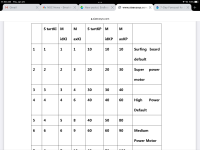
Comparing PID values already set on my controller (OEM?) to those in the manual’s PID table (see above post), I see that the assigned values put into my controllers PID values are “High Power” “Default” as viewed from the IOS Fardriver App running.

I have tried to change the 6 PID values to get the controllers PID values verbatim to read those in the category “super power motor”. I see from the manual that “the engineer will not let these values(column 4, 5 and 6) be changed.

Furthermore, the PID values in columns 1, 2 and 3 can be changed in the IOS Fardriver App and “save”ed but they are then not written to the controller as new PID’s so detected when the IOS App program is rebooted.

A recent addition to my Fardriver ISO App does say “Connected, Click here to Bound”. Clinking on that sends one to login. At login you are requested to either input a cell # or email address for a verification code. My cell # gets a window that says enter a valid phone number. I get no response in my mailbox when trying the email offer to get a verification code. Are only their dealers allowed to change PID’S?

Have you gone down this path to resolve what is going on with changing Fardriver PID’s? If not, then your comments so far have just been lip service and are not based on “hands on experience”. So, so far, no “super power motor” category for me but in a yard test I did manage to get 8400 watts quickly. No accurate response time to report, as I am waiting for the accuracy of an oscilloscope’s measurement.

If we cannot adjust the PID’s to get to the super power motor category, then Fardriver Controllers likely will be shy of getting to some presupposed benchmarks of supposed needed performance.
 
Last edited:
I don't have any experience with the Fardrivers, just the Phaserunner v6 and Lebowski brain and SFOC5 (Incememed) for FOC stuff.

I only seriously experimented with the various parameters on the SFOC5 (at least 6 or 7 years ago?), but I am pretty sure that the only time it actually blew up was caused by a motor winding intermittent short to stator, in combination with the "backwards" way the thermistor was used in that controller. But I vaguely recall warnings about not exceeding certain limits with certain parameters as the controller would *try* to do what you told it to whether the hardware could handle it or not. ;)

I have not yet finished building the controllers with the Lebowski brains, so no direct experience yet, only reading Lebowski's and Kiwifiat's (and others') posts about tuning them so I'll have an idea what to do (and *not* to do!) when I get to that point.

The Phaserunner, being based on the ASI BAC controllers (don't recall which one), has an advanced access to quite a lot of individual parameters, and I am pretty sure I have seen warnings to be careful with these, too. But I have only just started using mine, and it works so well even with the default settings (after having tuned it to the motor with it's autotune process) compared to previous generic non-FOC controllers that I am loathe to mess with it, especially since this is my daily commuter).

I have a second PR (v1? 2? not sure) that I got used, but I haven't hooked it up yet. Maybe once I have it on the other rear wheel of the trike I can experiment with the settings on that one.

Unfortunately I don't have the budget to replace these things if I blow them up playing around, so I can't really push them very hard. :(
 
If not, then your comments so far have just been lip service and are not based on “hands on experience”
That's seems a somewhat blinkered response. Just because your controller & app can't do what someone has talked about doesn't make it lip service.

I presume you've read the Fardriver thread & are fully aware of the issues around fardriver requiring all sorts of totally irrelevant permissions before it functions to the best of it's abilities (I won't say "well" or "properly"!). And the relevant shortcomings of each of the app & the PC software.
 
@ Bikerpete

Not sure many are intimately familiar with stomping down on a 300cc class heavy fly wheeled Trials machine when its good and wound up and let it go WOT with a quick clutch dump. :D I am just amazed how the whole thing fly's up into the air when you hit it just right. Also been the tennis ball in the dual ball drop example more than a few times so far when I get it way wrong.
 
bikerpete,

you said, “That's seems a somewhat blinkered response. Just because your controller & app can't do what someone has talked about doesn't make it lip service.”

We [you and I] do not know which controller he is talking about. How could I conclude it was mine?


From the web,

noun. Britannica Dictionary definition of LIP SERVICE. [noncount] : support for someone or something that is expressed by someone in words but that is not shown in that person's actions. She paid/gave/offered lip service to blue-collar workers, but she did nothing to help them.

To be lip service the talker would ………..offer superficial Support …in words… that is not shown in a person’s actions. Do you get it, how I properly applied “lip service”? His comments were just descriptive of which controller? Who knows? No concrete advise [that person’s actions] given to solve the problem at hand— just chatter—lip service - if you will.
 
Last edited:
My apologies for chattering. I was simply trying to suggest a path forward that I didn't know if you had already tried.

I used the wording I did (quoted below) because my reply was about FOC generally, but not every controller has the same capabilities.
FOC, depending on the specific controller design, can feed the current however you'd like it to. Some are tunable to the point you can blow them up by feeding the current too quickly and too hard. ;)

You're welcome to look around and read about all the different FOC controllers out there to find out what each one is capable of doing both in hardware and software, what parameters are tunable and to what degree, etc. I don't know which ones could do exactly what you want.

I'll stay out of this discussion from now on, since I can never have relevant experience to it. (I'm physically incapable of ever riding such a bike, and financially incapable of ever building one even if I could ride it)
 
@DingusMcGee In my world I've only ever heard 'lip service' being used in a derogatory manner, as your quote suggests.

As I see it, Amberwolf offered information that could inform a possible path forward, or at least some further knowledge. There was no mention of any particular brand of controller, nor need there have been, he obviously (to me at least) wasn't talking about any particular controller.
So I don't understand why you'd make what I see as a derogatory comment.
It appeared somewhat blinkered to me in that you didn't seem to recognise that he wasn't talking directly to your specific circumstances and brand/model of controller.
Maybe you didn't intend or see it that way - that's one of the problems with text based forums that so often leads to interactions that would rarely occur in face to face discussions, we often miss out on all sorts of cues that would exist in real-life conversations and that causes misunderstandings to occur.

I always try to work on the assumption that anyone who responds in a forum like this is genuinely trying to contribute in a positive manner.
My apologies for chattering. I was simply trying to suggest a path forward that I didn't know if you had already tried.

I used the wording I did (quoted below) because my reply was about FOC generally, but not every controller has the same capabilities.


You're welcome to look around and read about all the different FOC controllers out there to find out what each one is capable of doing both in hardware and software, what parameters are tunable and to what degree, etc. I don't know which ones could do exactly what you want.

I'll stay out of this discussion from now on, since I can never have relevant experience to it. (I'm physically incapable of ever riding such a bike, and financially incapable of ever building one even if I could ride it)
Noooo. Don't go 🙏
I've enjoyed your input. You don't have to be capable in order to have relevant understanding, but without understanding you can't be competent.
 
@amberwolf ,

Apologies accepted. You seem to be able to take this “derogatory” labeling in stride. SO thanks for paying lip service……

bikerpete et al,

Welcome to the world of Digital Deception. Whether your controller is Nucula, Fardriver, BAC or whatever, making programming changes to your controller in no way assures that you are getting what changes you have entered. One must perform real-time measurements of performance before and after to verify the changes were incorporated.

Such changes are subject to within the ranges of what OEM controller designers allow for changing the PID (Proportional, Integrative, Differential) variables. The controller may have pseudo updating. The change you post show up in the menu, but by the placebo effect we can feel the difference and are vicariously joyed by the new changes even though no changes where made to the PID’s. PID control systems measure/sample the variables ONCE over some small finite time interval and then allow the object controlled (BLDC motor) to evolve on its merry way until the next sample interval. Will the system stay stable over that the time duration when no monitoring happens? Not all possible PID variables keep the system stable.

Point in case. The CycleAnalyst can be programmed to change a throttle signal to WOT upon reaching the threshold throttle voltage. But the controller still does what the PID variables are programmed to do when encountering WOT. So unless the PID variables allow a real WOT signal to change the system as such, we only get what the PID variables allow.

Once we start needing changes over a small time interval, maybe say 1.0 second, we must use accurate timing and real measurements of the sought variables as opposed to just the feel.
 
Last edited:
Despite some uninformed Fardriver controller bashers giving bad mouth about the Fardriver customer service & permissions, I have found out how to change the PID parameters on Fardriver controllers to get a change from “High power Default” to “Super power motor”.

See my post: Nanjing far driver controllers. For more on this.

The change in performance is somewhat obvious just by the feel of the acceleration —150% more?— may be some measurements coming?

The 2 oscilloscopes I ordered came today so more accurate timing of the impulse = momentum change.
 
Last edited:
'uninformed Fardriver controller bashers' ? I suspect many of those people have an expectation that what's written on the tin is what's inside.
As you pointed out, you tried to change settings that appear in the app, but they wouldn't stick. So then you had to figure out that you need to set your phone date to last year and install a superseded version of the app to actually get access to the settings.
That's just one small example of the long litany of complications with Fardriver user software and interfaces. It's a constantly evolving shambles.

That said, the controllers are quite capable and functional, and they are good value for what they provide. Just don't pretend for a moment that they are a seriously high quality product in any respect.
I've got 5 of them here and they're solid once you've got them configured, but basically you get what you pay for.
My Nucular is vastly superior in almost every respect.
I rather lust after a Silixcon, I suspect they would be a really nice device once you learnt the complexities of their programming options.

I'm planning on putting my Nuc back on a bike because it's config allows setting not just throttle profiles, but also current rise rates - from 50 - 50,000 A/s.
I'm thinking I might be able to connect a cable-pull hall throttle box to a clutch lever with a very high leverage ratio so a small lever movement sends the throttle from 0-Max. Set the Nuc to 50,000A/s and That should be enough to see what the QS138 can do from standstill. Failing that I might resort to a simple switch cutting in full throttle signal - that seems a little nerve wracking, but I'm pretty confident of my clutch pulling reactions.
My Nuc is only a 12F, so the controller/motor combo maxes out at around 8.5kW I think it was, but it should be sufficient to get a feel for the nature of the response I think.

I've done some calcs on output sprocket torque produced by a 'typical' ICE trials flywheel under different scenarios and compared them to the QS138 chart and my DOB ratios. In theory the QS/DOB should be capable of somewhat similar output to a 125cc trials bike. Not insignificant!
There's a fair bit of unknown in the time taken to drop RPM, and I've also totally disregarded the mass of the ICE crankshaft assembly and any contribution from the engine itself.
But looking at a fairly wide range of scenarios suggests the QS/DOB shouldn't be too far either side of a 125cc, at least vaguely in the ballpark.
Then it just depends on the ability of the NUC to actually deliver those fast A/s rates, and the ability of the QS to respond while under real world loads.
We'll see.

I'm also slowly progressing on the design of a chain deflection tensiometer so I can get figures for actual rear wheel torque while riding real-world obstacles. I'm almost at the point of ordering two load cells, probably one 0-100kg, one 0-200kg. There's considerable fudge factor around both what the actual chain tension will be, and also how much deflection I'll eventually achieve in the device.
My calcs are suggesting 750kgf in the chain is not a bad working figure to start out with.
Load cells are so cheap it's not a big deal as long as both are the same physical dimensions and mounting.
I'm anticipating getting data at around 20hz. The load cell amp can send at 80hz, but I'm planning on doing some averaging and dropping high & low values before storing the data. I expect it's still going to be noisy as all get out, but with luck there'll be some sort of moving average that's useful. The figures don't need to be particularly accurate, just ballpark will be a big step forward. The rate of change will be at least as informative as the absolute values.
 
bikerpete,

Just so you are not uninformed about current Fardriver controllers and merely report your bad history, I have some news contrary to the info posted in your Rant.

Your rant does beg one question? that appears to be what a lot of the posters in the Fardriver thread hint they lack:

—- they cannot reads the manual and apply. Poor victims?

From dun electric store Malaysia: “The new controllers are all unbound versions, you can use the latest APP.”

You say 50,000 a/sec. Do you have a figure for the current rise rate for what LiPo’s produce?
 
Last edited:
bikerpete,

Enjoyed the rest of your rant.

Along the same lines of your testing I have an in line throttle signal intercept module that at the push of a horn button can add to the throttle signal voltage < 1.5v (pot adjustable from 0.0 v to 1.5 v) for the duration you hold the horn button down. The item is battery powered and Left hand operation. This is simpler than making Arduino.
 
Last edited:
It will be interesting to see how the torque sensor interplays with the suspension action pulling on the chain. I guess ultimately torque is torque whether its the motor moving the bike forward or resisting the suspension pulling on it.

I have wondered about this regarding mtb trials moves with a torque sensing bottom bracket. With my full suspension bike there is some chain growth and pedal kickback as the rear end moves through the stroke. I would not want a torque impulse from the motor during those times like landing to back wheel on an edge. I think most of the bike torque sensors require way more pedal rotation to start providing signal out to prevent runaway behavior.

I know bicycles are a bit of a tangent here but there is some antisquat behavior built into moto swing arm geometry so I would expect some torque spikes that arent necessarily coming from your throttle input.
 
DanGT86,

If your MTB does not have anti-sag suspension, then an increase in chain tension will cause an unweighting on the rear wheel, making rear wheel spin easier.

The old Spercialized Big Hit downhill bikes do have anti-sag rear suspension. A burst on the throttle will cause the seat to rise which jams the rear tire towards the ground.

I have a Brodie Thumper which does not have anti-sag suspension and the rear wheel loses traction upon harder accells because of lifting on the swing arm.
 
Last edited:
On my ICE trials bike the drive sprocket is set inline with the swing arm pivot with normal weight rider static loading the suspension. Somewhat set there as most understood to best balance the torque induced squat behavior. When extended it acts somewhat anti squat and when more compressed it adds to squat. I do not see this as what creates a significant portion of the lift we have been discussing (With regards to the well timed rider compression - clutch dump).
 
In regards to the simple analog throttle intercept circuit, I have it mostly built and housed in a project box.

To integrate this module’s manner of performance with the existing throttle demands of the controller circuit, state changes of these analog circuits need to be made quite rapidly. A SSR (solid state relay) likely will suffice.

State changes that happen:


States:

1. Throttle signal pass thru mode

2. Battery voltage adds your chosen voltage in series to the throttle signal to send a larger throttle voltage.

To change from state 1 to state 2 requires a disconnect in the circuit 1 and a connect to circuit 2. This logic function could be done manual fashion with a DPDT switch, but in terms of controller sampling rate the switch is too slow and I merely want to pulse hold the state of having additional throttle voltage.

Even though I have a grouping of different (SSR) relays, the ones that I have on hand that do the correct function need 12VDC to drive the relay/circuit. I suppose I could easily get 12v off the 5v lines with a boost converter which I have on hand.

The SSR most elegant for circuit simplicity would be low voltage (5v would work as the nearby throttle signal operates at 5v) and have pins for acting like a STDP relay. Then, with the push button engagement, the analog circuits set-up could be changed from state 1 to state 2 with sufficient change speed.

I will have to track down such a relay before reporting how the circuit works.
 
Last edited:
Back
Top