Outrunner left side mid-drive conversion

alpaca123

1 mW
Joined
Dec 9, 2021
Messages
15
Howdy,

After watching some videos and getting inspired to go a little deeper than a grin ready to roll kit, I thought I'd post my results of a mid-drive here to share. I love my front hub but I wanted to try something with better weight distribution, and less overall weight. I really like regular biking, especially the drive trains, so this was my approach to a mid-drive while keeping my regular drive train intact. I was not trying to make a motorcycle, just a decent moped.

I would like to specifically thank ES users @thepronghorn, @FZBob, @district9prawn, and @mxlemming. Their build posts showed me it was very possible to build what I wanted. I would also like to thank anyone who has posted anything, it's all good knowledge.

Motor: Flipsky 7070 110Kv (comes out at 118Kv from the baserunner autotune). From Amazon
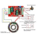
Controller: Baserunner L10 V3. From GRIN
Controller controller: Cycle Analyst V3 running 3.14 firmware. From GRIN
Battery: 48V 16.5Ah. From GRIN
One regular throttle 0-5V. From Amazon
One Ebrake sensor. From EM3EV
1/8'' 6061 Aluminum Custom sprocket*. From local metal cut/bend shop
1/8'' and 1/4'' 6061 Aluminum Custom motor mount*. From local metal cut/bend shop. Slotted holes for chain tensioning.
Several 10T-20T motor sprockets. From Amazon.

*Had to learn CAD and used FreeCad. FreeCad gets the job done, it's probably good for learning but I'm not the one to say. It struggles with some complex designs and you need to be really careful with your order of operations or it nukes your PC, or it nukes your model due to an internal bug. Considering it's free, its amazing.
1683572834371.png
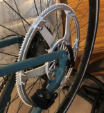
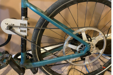
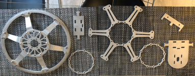
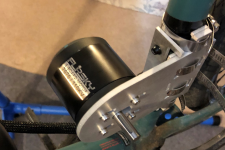
Motor mount has three pieces. One 1/4'' thick plate with slotted holes for chain tensioning. 44mm dia bolt array for motor mount and a slot for a 10mm shaft. Then there is a 1/8''' piece to space that plate out from the seat tube, taken from the same model but with most of it shaved off as it's just a spacer. Last piece connects to the bottle bosses and has some stick out parts to help align the other two plates. The whole mount is attached with 4 hose clamps.
1683572863204.png

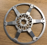
The sprocket is all 1/8'' thick plates, I had two designs, one with bent spokes that actually managed to work and one with flat spokes and spacers to push it out form the chain/seat stays. All held together with M5 hardware and nylocks. It attaches to the hub using the 6 hole disc rotor pattern. My current design requires that I sacrifice my rear disc caliper. In hindsight it is definitely possible to re-design my bent spokes to allow for regular disc caliper and rotor use. Design is for a #25 chain for maximizing teeth count for reduction purposes.
1683572936951.png1683572965986.png


So far it's running at 60%. I give it 60% because it moves, but won't be relied on for what it is.

First issue is I can't for the life of me get my hands on a #25 or #25H chain built to ANSI specs in a length longer than 16''. I have been through 4 10ft chains that are short in pitch by what seems to be just under 0.1 mm (crap calipers), and they end up not seating after 50-60 teeth of engagement, before seating again 20-30 teeth later. I have had a few 16'' timing chains (advertised as 10ft...) that measured perfect and fit perfect(or at least consistently with with craplipers). I compared the two types and the good 16'' chains were about 1 mm longer than their crap counterparts for the same number of links. I have another 10ft length on order from a hobby robots supplier in Canada so hopefully that will work better than the china chains I have used so far. Worst case I will link up way too many little timing chains (at least they come in #25H). Fixing this should put me at a conditional 100%.

Second issue is I can't get the baserunner consistently tuned. If I run autotune over and over I keep getting completely different hall configurations. Running sensorless fixes that issue but id like to have a bit of power from standstill without the sensorless jerk. Some of the detected hall sensor configs work for a period before I get an overcurrent fault, but overall the start is not that much different from sensorless. I plan on playing hall sensor bingo in the near future to see if that remedies my issues with the baserunner recognizing them. Regen seems to work on the bike stand but I have not used it under load.

When in use I have been limited to using a 20T motor sprocket to maximize engagement at one end (not a good gear reduction), and I have disabled regen so the chain only slips one way. It works but its way too spicy for anything outside of the back alley for testing, and I'd rather not trash my sprocket.

Anyone know of a place in Canada that will supply a good #25 or #25H chain without needing to order 500ft of it?

Anyone have any tuning tips for the controller? Or tips on the hall sensors? I think I have read most of the existing posts for base/phase runner tuning, I have had some trouble searching for what I need with hall sensors as the term is used a lot.

Thanks for reading, I will update with more info and photos as I get them.
 
*Had to learn CAD and used FreeCad. FreeCad gets the job done, it's probably good for learning but I'm not the one to say. It struggles with some complex designs and you need to be really careful with your order of operations or it nukes your PC, or it nukes your model due to an internal bug.

What specifically about OoO causes the problem, and what OoO avoids it? I ask because at some point I will have to start using a new CAD program to get some stuff done on various projects, and this one has come up a lot when I have asked / read about good free ones.


Motor mount has three pieces. One 1/4'' thick plate with slotted holes for chain tensioning. 44mm dia bolt array for motor mount and a slot for a 10mm shaft. Then there is a 1/8''' piece to space that plate out from the seat tube, taken from the same model but with most of it shaved off as it's just a spacer. Last piece connects to the bottle bosses and has some stick out parts to help align the other two plates. The whole mount is attached with 4 hose clamps.

FWIW, if you run into issues with twist (common for single-tube-securing kinds of mount designs), you can add a support from the front edge of the motor mount plate to the downtube, as straight out from the front of the mount as you can live with, to reach forward to the downtube (keeping this part in tension whenever the mount tries to turn on the seattube).


Regarding halls...do you have an oscilloscope? you can use one to see how noisy the hall signals are; it's not uncommon for hall noise to cause "random" problems with motor operation, where it works fine then doesn't, etc. If no scope available, you can still try some things to reduce the chance that this is causing it.

The noise is most often induced into the hall signal wires during high current events on the phase wires. When it's this, sometimes separating the two sets of wires physically from each other so they exit from different points in the motor and run on different paths from motor to controller.

Sometimes just shielding the hall wires with a foil wrap from sensors to controller, and grounding the shield only +at the controller end, may help.

Sometimes a controller design allows for a higher pullup voltage on the hall signal lines, going up to 12v instead of 5v, which increases the signal-to-noise ratio on the signal lines. (the power supply to the halls remains at 5v). I don't think the *runner series can do this; it would require internal controller modifications, or an external buffer module designed built and installed between motor and controller.


It could also be the hall placement inside the motor--they may not be close enough to the magnets to get clear signals--that can be seen more at higher motor loads (because the stator fields will be more likely to interfere with hall operation directly inside the sensor at the higher currents).

The RPM of the motor may just be too high for the controller to accurately read them if it happens only at faster motor speeds.
 
Regarding freecad, I don’t quite know enough about software to explain it properly but here is an example. If you look at my motor mount piece, there are no hard corners, everything is “fillet-ed” to have a radiused corner. If my made a blocky 3D shape, then smoothed it out in 3D my computer would slow right down. If I radiused the corners in 2D, then extruded to 3D, it would not slow down my computer, but took a bit more effort as I’d need to constrain the new curved corners. I believe freecad tries to re-calculate and re-render everything starting at step one; the more individual steps you have the more calcs it needs to run to produce a result; a complicated 2D sketch being extruded is easier on my hardware than picking away or adding to a 3D shape. They have a naming issue too I encountered you can read up on, it happens when you have a model with lots going on and can really screw things up. Either way their wiki site / forum / manual is really good and there are a lot of useful plugins. Worst case I’ve been able to google solve all my problems with it.

Good to know about the Down tube idea, I haven’t been able to run it hard enough to have that happen though. I will keep it in mind.

Thanks for the info on the hall sensors, I don’t have an oscilloscope and would rather not mess with my controller internals. I could see the high current issue you brought up being a thing, usually (when hooked up to my computer to I can see, the problems start with a current fault. I also wouldn’t be surprised if the thing just spins too fast for the Baserunner, although I think I saw a video where grin had a Phaserunner working with an rc motor at 7000 rpm.

I plan on redoing my connections for the sensors. I still want to run through the six possible configurations of sensors just to make sure there isn’t a wire colour discrepancy. I was thinking of splitting the 5 signal wires into a 3pin (halls) and 2 pin (5v, ground) connector, to make future changes easier. Based off what you said is there a potential for a better result if I split that differently (would want to isolate the issue first though)? Either way sensorless seems to work exactly as intended, and works great if the motor is already spinning.
 
Regarding freecad, I don’t quite know enough about software to explain it properly but here is an example.
<snip>

Thanks--that helps. There are similar issues regarding extrusions (worse the more complex the shape and the type of extrusion--path extrusions can really mess with things, such as to make a helical gear, etc) in my ancient version of Lightwave3D (which uses a parallel-port Sentinel protection dongle...which is part of why I need to learn something new--IIRC it's at least $100 to "upgrade" to a USB dongle, and I don't even know that it will run correctly on modern Windows).


I plan on redoing my connections for the sensors. I still want to run through the six possible configurations of sensors just to make sure there isn’t a wire colour discrepancy.
Can't hurt, but the controller should be able to automatically map the right order during autotuning. It also should have something in the GUI to show you the hall/phase order of sense vs firing, kind of like those motor testers do, but I might be thinking of VESC or one of the other FOC controller setup programs.

I was thinking of splitting the 5 signal wires into a 3pin (halls) and 2 pin (5v, ground) connector, to make future changes easier. Based off what you said is there a potential for a better result if I split that differently (would want to isolate the issue first though)? Either way sensorless seems to work exactly as intended, and works great if the motor is already spinning.
I don't think it will make any difference to split hall power and ground from the hall signals--any noise on any of them could affect the signal, but noise on one wouldn't induce into the others.

If sensorless works perfectly (other than from a loaded stop, but without errors then, just not as clean a startup), but in sensored you get errors (because the controller is trying to drive the motor wrong because of bad sensor data) then the big question is:

--Does the problem with sensored occur under higher loads (currents), or at higher speeds? (or is it the same regardless of conditions)

Either one could be a signal degradation or quality problem, but caused by different problems.

Higher speeds could be the signal being too short to be read correctly, especially if there is significant noise in the signal.That can even be wrong kind of halls used for the motor type. ****

Higher loads could be the signal being degraded by induced currents either inside the motor itself (stator fields interfering with rotor magnet fields, usually a hall placement flaw), or in the hall/phase cable.

Sometimes it's even just a bad ground in the hall signal cable, leaving the controller without a good reference for the signals it is getting. This would probably have about the same results regardless of load or speed.

**** There are bipolar latching halls, whcih are the most common type in DD and geared hubmotors, but there are also unipolar latching, and nonlatching of each, which can be used in any of these motors. If the motor spins fast enough and there are few enough poles (magnets) the sensor used in that motor might not give as long a signal as one of the others. A bipolar will give the longest signal, because it takes two magnets passing it to switch (only switches when the polarity changes). Unipolar switches anytime the field strength changes above/below whatever gauss limit it is built to. Latching holds the output until a field change. Nonlatching directly tracks the field; not enough strength and it "lets go", turning off.

All those are open collector output, so when the turn on they ground the output, when off the output floats so pullups to a voltage are required inside the controller or you just have noise. The greater the pullup voltage, the greater the difference between the on (grounded) state and the off (pulled up) state, so the greater the noise immunity--less likely to have noise spikes as large as the active states so easier to filter out in the software (or hardware) inside the controller.
 
Thanks for posting your bike!

Your motor mount is interesting. Hopefully it stays put. The left seat stay on my bike does not allow me to mount my motor there since it interferes with the chain.

Hopefully the hobby robotics chain works for you. I bought my chain and chain tool from Swyft Robotics here in the US. They do ship to Canada if you are really running out of options. Did you chamfer the teeth on the sprocket at all? My chain was a pretty tight fit initially, but it's given me no problems on the bike.

As far as your FreeCAD struggles, I experienced the opposite issue in Fusion 360. If I circular pattern all 132 teeth for my sprocket in 2D, it takes forever to render. However, if I extrude a little 1/132 pie slice then circular pattern 132 3D slices, it works great.
 
@amberwolf

I have done some custom bolts/nuts in freecad for 3d printing and the helical functions in freecad worked without any issue, lots of tutorials and instructions online as well for that.

To confirm, the hall order should come out as the below over one motor rotation (for Halls named 1, 2, and 3 to show their order)? The phaserunner suite has a thing showing what halls are being detected depending on motor location.

1

1-2

2

2-3

3

3-1

I re did some connections last night, and found one loose-ish hall connection, but did not have time to check with a computer. I will update once I have time to check.

The sensored problem occurs any time loaded or unloaded, inconsistently, but still ~50% of the time. Hopefully it was just a bad connection and/or wiring order.

The motor is rated for 4000W, 100A, and an 18S battery. I am running less than that (I think) for all those parameters. I capped the baserunner at 1000W, 70A, and use a 48V battery.

Most of what you said is way over my head for understanding but I will try to learn and see if it helps out. Either way, sensorless operation seems to work fine. At this point I'm still thinking it's a user installation error / lack of understanding that's the root cause of the issues. I will reach out to GRIN to confirm I am using their software and controller correctly if my problems persist.

@thepronghorn

I am glad I finally had something to post!

I have a lot of faith in my four hose clamps, I underestimated the precision the metal shop had so my bottle boss piece does not lock in the other pieces as I wanted it too, it just aids with alignment more than anything as I can square the mount off of it.

I did chamfer the sprocket by hand, I extended the chamfer just past the roller trough but ended up with a sharp tooth section profile instead of a trapezoid. I only did this because I had not yet found that my chains were out of spec and I thought they were not seating far enough down, causing them to come up short. The correct spec shorter chains sat on easy with very little slop with the chamfer. In the future I may just get a thinner plate made of 7075 so I can keep a full rectangular tooth profile.

@SlowCo

Thank you!
 
Nice one. Keep posting pics!

I fear you'll find the same as me, you forever want a bigger motor. The little flipsky is going to struggle, but depends on your expectation.

Look out for the out of plane forces that can twist your mounts around.
 
The new chain came in, and it is made to spec. If you are in Canada I used this website: iDESIGN Solutions - Canada's Technology Store for Schools & Businesses. Put it on and tightened everything up and went for a proper test ride. Everything worked well. Used a 12T sprocket. @mxlemming so far overall power is good enough, although low speed performance could be improved.
1684418333461.png1684418365722.png1684418386691.png1684418410660.png

-No stuttering while riding.
-No mount twist, but watching that.
-Motor shell was warm but not hot after 15 min on flat with some regen testing and the above speed test.
-Motor shell was hotter, but very touchable after a steep hill test at a low speed.
-Performance from stop was alright, pedaling required to get going. No wheelies.
-Between 10ish-30ish km/hr throttle response was good, fun to ride and quick to respond (no pedal). Decent for wheelies/manuals (is it a manual if I throttle??).
-Over 30ish km/hr throttle response decreased (no pedal). Too scared to wheelie/manual at these speeds.
-Throttle response improved alot with pedaling and was responsive up to max cadence/gearing (40:11, 44ish km/hr).
-Variable regen worked, but was pretty weak at high speeds compared to my DD front hub. Used 0.8V-0.0V on the CAv3/Baserunner.
-Way lighter in mass than my front hub set up, and weight distribution is better for throwing the bike around. (I have to carry it up/down 2 stories/ride).

Issues/first world problems:
-Loud has hell, but 50% seems to be the motor itself not just my home designed chain.
-High motor RPMS migrated up seat tube into seat causing slight taint tickling
-Speed cable from motor does not register anything. Emailed GRIN to see if there is a work around.

Next steps for the long weekend considering it looks like it will be too smoky to ride for a long time:
-Put on the suspension seat post I gave up on because the post was too short for good pedaling power.
-Try out my 10T sprocket.
-Fiddle with chainline as its not 100% perfect.
-Fine tune regen settings for better engagement when I hit the ebrakes.
-Fine tune all power settings to maximum with a buffer so I don't blow anything up. Goal is to drop the CAv3 to save on wiring rat's nests.
-Look into a torque sensor.
-Revisit hub mount to see if I can get my brake back on. Look into a BB area mount.

Dream:
-Variable regen brake lever, even if it can't actuate brakes*

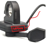
*I found out by accident that if you place a reed switch brake sensor at the location below on one of those cheap lateral thumb throttles it gets triggered by the throttle magnet. If you have this hooked up properly to a variable regen device like the CAv3/BR you can mount the throttle backwards to get a variable trigger brake.
1684418152031.png1684418207037.png
 
Dream:
-Variable regen brake lever, even if it can't actuate brakes*
If you're using cable-operated brakes, you can make one that will operate both the variable regen and the mechanical brake (and a brake light if you like).

See this thread for what I use on SB Cruiser:
The also-operating-mechanical-brake I haven't implemented yet, but I have a dual-cable-pulling ATV lever that also has a brake switch in it (I also have a bicycle dual lever but it has no switch, though they do make those too).

In my case I'm using the Cycle Analyst(like you are) to process the ebrake controls because the controllers used at the time (one still is) the Grinfineon that only has a single variable input (like the *runners), so the CA is designed to send a variable throttle *below* 0.8v for the variable regen control, whenever it detects an ebrake signal, if you set this up.

If you have an FOC (or other) controller with a separate variable input to control braking force, you can directly connect it to the brake lever's variable output. (you may not need the switch to be in the lever, either, but that's still handy for brake lights).


*I found out by accident that if you place a reed switch brake sensor at the location below on one of those cheap lateral thumb throttles it gets triggered by the throttle magnet. If you have this hooked up properly to a variable regen device like the CAv3/BR you can mount the throttle backwards to get a variable trigger brake.

That's interesting. :)
 
I was hoping to update this sooner but had some field work and personal stuff come up. Here is my essay for grading.

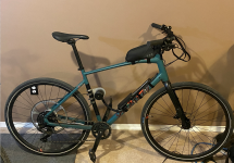
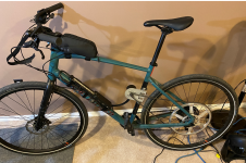
Running this bike with a power limit of 750-1000 W on the CAv3 seems to be the sweet spot for this 7070 motor / battery / controller / gearing. Works very good at typical cruising speeds (20-35 km/hr) and regen is quite powerful and functional. Using 12T:150T ratio, 10T:150T felt the same but was louder.

For better performance at slower/faster speeds, I think @mxlemming and many others are correct – need bigger motor, need more metal. Probably need something with registration and insurance.

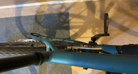
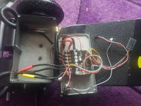
Bike config with wiring: see photos.

Handlebar config:

Left side from outside inwards: Grip, brake lever (unattached to physical brakes) with brake sensor, thumb throttle, bell.

Right side from outside inwards: Grip, Brake lever (attached to front hydraulic disc brake) with brake sensor, trigger shifter.

I swapped the brake line around because I did not like having my thumb on the throttle concurrently with fingers modulating the brake lever. My shifter is bulky as hell so there is no room on the right for a thumb throttle in a good spot.

I had some issues that got solved so I summarized them below, hopefully someone else can learn from my mistakes. Big thanks to Hayley and Justin at GRIN for giving me some pointers over email. I have seen some threads indicating poor response times recently; I did not have that, only prompt responses, with useful answers. Big thanks to @amberwolf too, your suggestion to move wiring away from other wires solved some issues that seemed to be related to signal noise.

Issue: Battery shutting down when in use (throttle and regen).

Cause: Not paying attention to setting changes when loading defaults in the phaserunner suite. I had set my battery current limit to the BMS limit (d’oh!). Looks like those safety features work!

Solution: …pay attention and change settings back as required! I didn’t piece together that the phaserunner suite defaults overwrite motor, controller, and battery settings when loading defaults. Somehow missed this even though I was playing around with the max regen current (d’oh!).

Issue: Instantaneous Phase Over Current faults.

Cause: Current regulator bandwidth and PLL Bandwidth were set too low for my motor, motor and controller were working with motor rpm not wheel rpm.

Solution: Trial and error process of increasing them, then decreasing to find a sweet spot for function. This is indicated in the manual and was also told to me by GRIN. Setting the motor/controller to reference wheel speed also helped. Did a new autotune with Kv and pole pairs adjusted for gearing. Kv(adjusted)=(motor Kv)*(motor:wheel ratio) pole pairs=(motor pole pairs)/(motor:wheel ratio).

I have also concluded (not that I am an authority) that hydro brakes outside of DH mtb are pointless, especially with 160 or smaller rotors. Any utilitarian riding would be better served with mechanical brakes so you can fix them on the go (assuming you don’t need to ride DH mtb to the store or work; if you do need to ride DH for errands/commute please send me your address so I know where to move 😊).
 
Hello,

You have a tensioned chain without a tensioner. I'm interested in your experience with that, as that is part of my design too (see signature).

I'm currently looking into replacing that with a Gates belt, but I'm only certain of a chain working now. A fellow who supplies track sprockets says he's never seen a sprocket last longer than 4,000 kilometres - but that is using 1/8" bicycle track chain.
 
i have an outrunner project waiting in the wings using a 6384 - 120kv (sensored) motor. i will be using 20inch wheels with a 10:1 single reduction. would a 36v 20a controller give me enough power? not looking to go fast, 20-25mph is fine.
 
i have an outrunner project waiting in the wings using a 6384 - 120kv (sensored) motor. i will be using 20inch wheels with a 10:1 single reduction. would a 36v 20a controller give me enough power? not looking to go fast, 20-25mph is fine.
Unfortunately it's not enough info; power usage at a speed depends on conditions (wind, terrain, aerodynamics of the bike/vehicle, etc.

To know if it is enough power, the first thing you should do is determine how much power your bike will need to do the job you need it to do under the conditions you ride in, and teh way you ride. (hills, wind, road conditions, speed, acceleration, etc) You can use the motor simulator at ebikes.ca to guesstimate the power for various conditions.

Once you know the power necessary, you can pick a motor and controller that will do that job under those conditions. This also lets you get a battery that can supply the necessary current to run those, and be a high enough voltage to give you the speed you need with the motor you choose and the gearing you are planning on.


Then you can also use the information from the simulator for Wh/mile or Wh/km to guesstimate total Wh required for the range you need, so you can get a battery with enough capacity.
 
thanks Amberwolf, i guess i will just have to give it a try and see how it goes. this is not my first rodeo but i have never tried R/C motors on a e-bike.
 
Apologies for the late replies I have been busy with life.

@offGridDownUnder My tension system is just slotted holes for the mounting screws. I set chain length with the motor ~1/4 of the way from the shortest side, gives me 3/4 of the slot length to tension, and 1/4 of the slot to slacken for sprocket removal as I was swapping some sprockets around with similar tooth counts. I checked it before every ride, but did have some slippage. Might try some tooth washers in the future but the best bet would be to get a motor with mounting holes larger than M4 so I can torque them harder. Although I imagine we have similar free lengths of chain, maybe the total engagement of my chain relative to total length makes it less prone to feeling the bad effects of a slack chain?

@crazy dreamer that's out of my scope of knowledge but post a thread when you have it running! Looks like @amberwolf has helped you anyways. Are you using an RC controller, my baserunner runs the motor very loudly. I was wondering if swapping to a esk8/rc controller would help that.

General update:
I used the bike for commuting for while and some cruises near my house. It works awesome however the motor runs very, very loud, not sure it that's just the motor or the controller. Overall the chain is surprisingly quiet. I did end up swapping back to my hub drive for now, for the noise and the below more pressing issue:
I had perpetual issues with my battery dying on me while riding. I normally have the CA a bag, so I mounted it, and saw on a subsequent ride that I was having voltage sag before it died, far too soon off a fresh charge. While playing around with settings during set up I certainly had IPOC issues, but those would shut down the baserunner not the battery, and were solved with a on/off. I also reduced the max regen current and battery current relative to the hub motor profile. *I did not check cells or open the battery case, but if I went to recharge, the satitator charger indicated nothing odd (Ah charged matched those used). After remounting, the hub motor has the same range and power as it did before.*
On my last ride, it died as usual. After letting the battery chill out and come back to life (back up to the voltage it was at before the insta-sag), I hooked it up to my PC/phaserunner suite. When I turned it on, I had a "Max Regen Voltage Rollback Active" warning. I haven't tried talking to grin about this yet (they helped me dial in my IPOC issues) as this setup is not in use, but I am wondering if the motor is generating way too much regen current for the baserunner/battery, regardless of setting used. Note that I charge my battery to 85% so I should always have room for some regen. I can't disable regen as I need to dismount my rear brake for this set up and need something in the rear. Anyone have any input or suggestions for me to try when I have time? I have since used the hub motor for a couple weeks and capacity and performance of the battery is surprising close to where it was when I purchased it three years ago.

Alpaca
 
I used a 7070 and had decent performance considering the motor size/mass. 83100 should work better as long as your voltage-Kv-reduction is set up correctly. I also tried something close to a 6384 from freerchobby at first, but swapped it out playing around with things and just stuck with the 7070. I am curious about going back to the 6384ish motor to see how that runs.

Not sure what your drive train plan is but see my posts above about chains if you go that route, with smaller pitches you need something made better than amazon specs.
 
Back
Top