eMark said:
Actually, i would be most interested (as would others) in what S/P wiring you believe is best as it isn't irrelevant and was the reason why i started this thread.
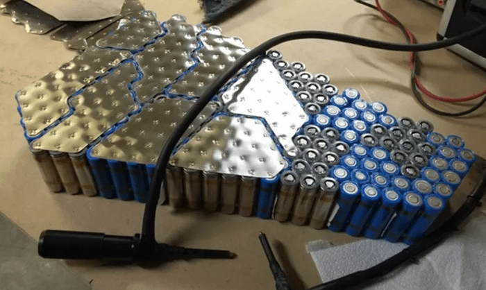
Other than as I noted before, of just using single large plates to make the serial and parallel connections at the same time, I don't have a preference, as I don't have any personal empriical testing as to which way to lay the interconnects (series first or parallel first).
")
If I go purely by theoretical stuff, I'd say that what Spinningmagnets said makes sense, about the series resistance. One thing you want to do in any current-carrying circuit like this is lower it's resistance, because all resistance does is waste power as heat, instead of allowing you to use it for useful work.
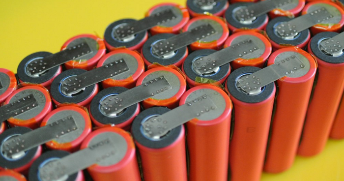
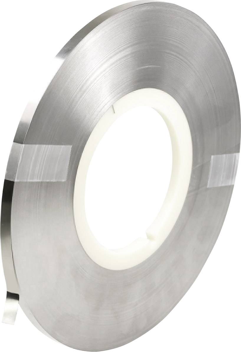
That's one of the reasons it may be preferable to use single large plates for each set of parallel cells, that make all the series and parallel connections for that group at the same time. It also lessens the resistance in boht series adn parallel paths, because ths plate is wider (and potentially thicker) tahn common nickel strips.
It's all interesting, but grasping with the fundamentals; especially the use of to or not to use a BMS in lieu of using a RC balance charger.
That entirely depends on your preferences, and your dedication (or lack thereof) to pack maintenance. If you want to just ride, and not worry about anything other than plugging the charger in when you finish a ride, then a good BMS on a good pack will let you do that. If you like to tinker and test, then either no BMS or just alarms and balancers (or manual balancing), or various other methods, might be your thing. Or a BMS with bluetooth that lets you monitor everything on your phone...
If you use a dependable RC charger, you're covered for charging and balancing. But you don't have anything to protect against overdischarge while riding, unless you use some form of cell-level monitoring (like cell alarms).
If you use a BMS, there are at least several types, from cheap to pretty expensive. If the pack itself is cheap, you don't want to spend a huge amount on the BMS. But a better BMS does a better job of keeping the pack safe, and can make it last longer, so it's a compromise for what things are important to you.
The crappier the cells are to start with (or the less suited they are to the project they're used in), the more you *need* a BMS (or something) to help them not die quickly.
The better the cells are, and the more closely matched they are (from same batch, etc) and the less hard they are pushed, the less you need a BMS (at least until the cells age and begin to drift apart in characteristics).
For instance, on my SB Cruiser trike's pack made of EIG NMC cells, I don't use a BMS because they stay balanced, and I don't use them anywhere near their capabilities 99% of the time. Every so often (maybe once a year, or even less often) I"ll check the cell voltages, just in case. So far, only once (on an older pack of these cells, used a little harder than the trike's) on an older bike, has a cell been out of balance when checked, and it was a bad cell (internal resistance went up significantly).
On a cheap 18650 pack Iv'e got, if it didn't have a BMS it probably would already be toast; even with the BMS it's not very good, and the BMS it has is not very good either (sometimes kinda "locks up" and doesn't allow further charging and doesn't balance, until it's discharged sometimes a fair bit). The cells it's made of are not designed for the use (discharge rate/etc) the pack was advertised for, either--the pack heats up quite rapidly.
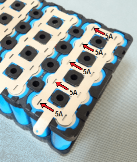
where would you attach the balance leads of either a BMS or a RC Balance Charger to the cells in that bottom right diagram.
It doesnt' matter where the balance leads are attached. They can be wherever physically works for a particular pack construction. The only necessity is ensuring each parallel group has a balance/sense wire to the appropriate BMS/etc pin.
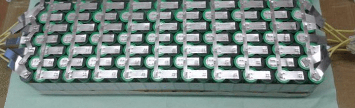
One would hope that we all can agree on the S/P expression for that bottom right diagram
All of those packs have the same S/P:
3S 4P
You can call them 4P 3S if you want. Doesn't matter.
As I said before, every one of them is exactly the same, electrically.