Parallel multiple brushed controllers on one big brushed motor

matt912836

100 W
Joined
Nov 25, 2012
Messages
126
Location
New York
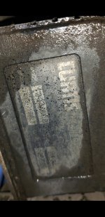
It's for a cargo trike which had a BRUSHED 12v 275a CURTIS controller on it. Its running a rear mounted mid motor, haven't got a good look at the motor itself, but if its running this controller then clearly it can take some power. Im looking up a replacement controller seems pretty pricey, so as a short term until i figure out a more modern motor to throw in it, im thinking of wiring 2 or 3 cheap 24v 1000w controllers wired in parallel, as a quick and cheap fix.

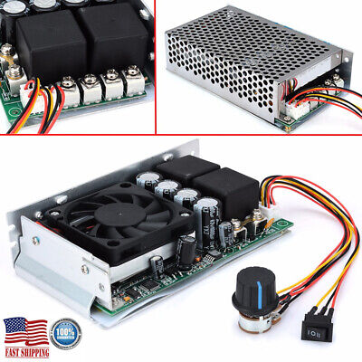
Right now Im running just one 24v 500w controller to test out and it gets the trike moving, but definitely needs more amps to carry any decent load or go up any hill. I don't think I need its full power, I feel 100-120a at 24v should be enough, and an overall speed increase is also welcome which is also why I'm upping to 24v. 24v 120a is about 2800w vs the original controller's 12v 275a being 3300w so it shouldn't be any real strain on the motor.

3 cheap 45a controllers are still way cheaper than a $300+ curtis, so is this even possible if all the controllers are identical? I know with brushless it gets way more complicated with halls sensors but apparently with a brushed system this shouldn't be a big issue.
 
If you are willing to disconnect the powerstage's gate drive control inputs from their controlling signals on all the controllers except one, and the tie in all those to that one's controlling signals, then you can parallel all the powerstages to one motor reasonably safely; it will be as if that one controller is just a lot more FETs in parallel. There will be some timing differences depending on length of gate drive control wires, but if they're all pretty short it should still work (I recommend using twisted-pair wiring for these signals).

But if you use them separately, then their PWM timing will all be different, and unless they are not typical half-bridge (or full bridge) powerstages, and are all instead just using simple grounding FETs to the motor negative wire, you can end up with shoot thru from one bridge to another, essentially shorting directly from battery positive to battery negative, and it may destroy the FETs in the bridges. The typical failure mode for FETs is stuck on, shorted, and in that event your motor will probably be stuck on full power, with no throttle control. If they fail open, then you just don't have any motor power anymore.

If the design of the bridge doesn't use the top FET via PWM, but only as a flywheel diode, it may not be a problem.

As long as there is never a top FET and a bottom FET in any of the controllers turned on at the same moment, there wont' be an issue with shoot-thru, but if any pair (even in different controllers) are turned on at the same time, that's when it's a problem.


A pretty good page about bridges (other pages have other good brushed controller info)
 
BTW, what happened to the Curtis? If it failed, there is probably a reason, and that might cause the new ones to fail as well.
 
As long as there is never a top FET and a bottom FET in any of the controllers turned on at the same moment, there wont' be an issue with shoot-thru, but if any pair (even in different controllers) are turned on at the same time, that's when it's a problem.
I don’t know much about brushed motors, but my fundamental assumption is that they output DC to the motor, which is probably an oversimplification. That said, what would happen if diodes were added to the controller outputs before paralleling them, and all controllers were just run off of the same throttle signal?
 
They work the same way as brushless controllers, but with only one or two bridges (like phases in BLDC).

So they also use PWM to turn the bridge FETs on and off, which slices up the voltage to the motor to create an average voltage to cause it to spin at a particular speed.

They don't send an actual steady DC voltage to the motor--like the BLDC types, they depend on the motor's properties to smooth out the pulses of voltage into constant rotation.

If you really want to know the details of how they (and pretty much any motor controller powerstage) work, that 4QD website is pretty good at explaining. (it's where I started learning about this stuff way back when)
 
I think it would be cheaper to do it right:

Wasn't sure if that would pair well with a hall sensor throttle but that was one of the options I was looking at, maybe I'm overcomplicating this.

Here's the motor it came with, anyone help identifying? I'm thinking its a LEM 170 but can't tell, and looking at the specs it just might be a bit overkill for my needs, and also feel only 100a may actually wind up hold this motor back.


Trying to figure out the exact model of this motor, no labels in sight and its filthy. The trike came with a 12v 275a controller, so i can only assume this is a 24v rated motor, the LEM170 is rated for 240 amps and the LEM200 is rated for 270 amps... Whats the chances this is a lem200? 😁 
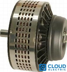
maybe a motor good enough for a two wheel build with a full amperage controller...

so for now, im thinking of just taking it out and bolting on my 6kw cyclone for the meantime, since I already have many brushless controllers capable of driving that just fine and wouldn't cost buying anything extra
 

Attachments

  • Screenshot_20240320-120652_Gallery.jpg
    Screenshot_20240320-120652_Gallery.jpg
    541.2 KB · Views: 4
  • Screenshot_20240320-120704_Gallery.jpg
    Screenshot_20240320-120704_Gallery.jpg
    317.5 KB · Views: 4
What model is the Curtis controller?
later floyd
 
What model is the Curtis controller?
later floyd
Curtis 1204-608 if my eyes don't deceive me, Not sure if it actually works or not, decent chance it actually does, I just didn't want to have to make and run a super high amp 12v pack for it 😅 I have enough 36-48-72v higher voltage packs lying around id rather get it to work with...
 

Attachments

  • Screenshot_20240320-132301_Gallery.jpg
    Screenshot_20240320-132301_Gallery.jpg
    691 KB · Views: 3
Back
Top