Power wheel - switch and or relay?

torker

100 kW
Joined
Oct 16, 2008
Messages
1,693
Location
Udall, Ks.
Hi all. Working on sprucing up a power wheel for the next grandbabies in line.
It had lead acid now I am going to use a lifepo4 I have. I am going to fab a steel enclosure for it.
The old setup use to melt the switches for fwd rev and hi low . I used the plastic 6 pin on-on switches it came with. I am considering using metal clad 30 a switches.
Wonder if these will hold up better. I will have to snip the connector and use separate connectors.

Also wondered if I could add a relay to the system to ease the load on the switch.

The switches I am talking about.
 

Attachments

  • Screenshot_20221217-183421_Firefox.jpg
    Screenshot_20221217-183421_Firefox.jpg
    437.6 KB · Views: 248
  • Screenshot_20221217-183603_Firefox.jpg
    Screenshot_20221217-183603_Firefox.jpg
    468.1 KB · Views: 246
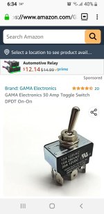
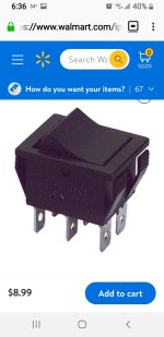
The metal toggle switch is a better bet than the plastic rocker switch for high current, depending on the specific plastic each is made from--but it is much more likley that all the important parts inside the metal toggle switch are more heat resistant, based on the many switches I've disassembled after failures of various kinds in all sorts of applications.

Usually a switch really capable of higher current will be physically larger than one that is not, given identical construction otherwise; it's usually reflected in the size of the contacts inside, and the connectors outside. (the actual toggle, slide, or rocker could be huge just for user interfacing but not have big contacts/etc).

The metal toggle switches are usually made in various contact position / spacing types, so you can probably find one on Mouser or Digikey that will directly fit your existing connector if necessary--easiest is to use their online chat to have someone there find the right part for you, given the info you have from your existing switches.

Or if you want better contact with less resistance, just insert your wires directly into the holes in each contact, then twist each tightly into a "noose" (lots of images online for good ways to do this), then solder to secure them (the solder won't be making the electrical connection if it's done right).

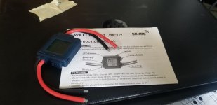
If you don't already know the actual peak and continuous current flow thru the switch when riding, you should measure that so you can be sure of getting a switch that will handle it.


Automotive relays can also be useful for using a smaller switch to pass a bigger current; I used some from the OnlineLEDStore on Amazon
https://www.amazon.com/gp/product/B01NBAO1SA
for various functions on the SB Cruiser when I rewired it a few years ago. None of them are used anywhere near their current limits, so I have not had any relay failures or blown fuses, though I did have one of the built-in fuse holders get finicky so I replaced the relay/fuseholder assembly (they just plug into the sockets so it was easy).

I don't know if those specific ones will work for your purpose; you'd have to know the peak and continuous currents they'll have to handle.
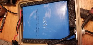
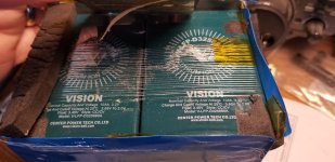
Note also that the lead-acid, while may sag a lot in voltage while doing so, may be able to provide higher current than the LFP pack (depending on what exactly the LFP is and what BMS it has, and how old the pack is) since those are often rated at only 2-3C or less.
 
Thanks AW. I am going to use the lifepo4 batteries I posted. Not sure the amps on the bms.
 

Attachments

  • 20220810_153358.jpg
    20220810_153358.jpg
    2.5 MB · Views: 215
I opened the others I got , they are cube instead of flat.
 

Attachments

  • 20221113_103536.jpg
    20221113_103536.jpg
    2.2 MB · Views: 215
  • 20221113_103124.jpg
    20221113_103124.jpg
    2.2 MB · Views: 215
Also I picked up this. I could come up a variable load and see what amps the bms tripps
 

Attachments

  • 20221218_130121.jpg
    20221218_130121.jpg
    2.1 MB · Views: 213
Would a circuit breaker be proper?
Like a blueseas 30amp 65v toggle switch circuit breaker?
 
That won't switch current flow directions as is needed for the motor to change direction from forward to reverse. It will just shut power off.

You could use circuit breakers to do it, but it would take four of them, and you'd have to make sure to turn off both the "forward" ones before turning on the "reverse" ones, or else you could short directly across the battery with them.
 
I am going to Grainger today and pu a better switch. I figured I would need 4 relays since this switch powers 2 circuits at once. 2 for forward and 2 for reverse.

Pretty sure my lifepo should be fine this buggy has a 10 a circuit breaker already.
 
You only need one relay, if it is a DPDT (remember the single DPDT switch controls everything by itself). Then you only need an SPST switch (that only has to handle the coil current) to turn the relay on for reverse, or leave it off for forward. Wire the relay the same way you'd wire the DPDT switch.

The breaker (or fuse) isn't really there to protect your battery, so it isn't sized to do that. It's sized to protect the wiring (and possibly motors) from catching on fire.

The BMS in your battery, if correctly designed, is there to protect the battery, but as you can see in a recent thread by Methods about Daly BMS, they are not always correctly designed and cannot always protect the battery against a short circuit, etc.
 
"only need one relay, if it is a DPDT (remember the single DPDT switch controls everything by itself). Then you only need an SPST switch (that only has to handle the coil current) to turn the relay on for reverse, or leave it off for forward. Wire the relay the same way you'd wire the DPDT switch."

I want to make sure that the kids only have one switch to get right. Just forward and reverse. Are you saying just use the relay for forward. That makes sense.
 
You'd actually be "using" the relay for reverse. If the relay doesn't work or isnt' turned on for whatever reason, the default wiring of the relay would be forward, to ensure normal operation "failsafe". :)

Look at how your original DPDT switch is wired, so that it swaps the polarity of the voltage fed to the motors. Do the same thing with the DPDT relay contacts, with the forward direction wired so that it works when the relay coil is not powered. Then use the small SPST switch to connect the relay coil to voltage, so that when it is on, the relay changes to reverse wiring but when it is not on the relay uses forward wiring.
 
Back
Top