Pre-Charge Resistor help

ah yea. I don't want to do the whole, resistor constantly ON thing..

I opened up the controller and it has approximately 1200 uF of caps in it. The 50 OHM 10 watt resistor is therefore good for a .25 sec precharge.. so i will use 2 in series for a 1/2 sec precharge time. Should be a lot easier on the caps.. !

Would an oscilloscope be good for measuring the amp/v levels? I have never owned or used one.
 
An oscilloscope is purely a voltage measuring tool, if you wish to measure amps, I would go with a dedicated ammeter. A good multimeter will do it, but they generally cant handle more than an amp or so.

There is no real need to measure the current through your resistor, so long as you know the actual resistance of your resistor, as well as the voltage of the pack its quite easy.

amps = Volts / Resistance 72V/100ohm = 0.72 amps (If your voltage is really this high, I would go with a larger power resistor, or a larger value resistor, as this is over 51W going through that resistor.)

So long as your are not in super-conducting levels this equations is for all intents and purpose's correct.


As a bit of a warning to anyone thinking of forgoing a pre-charge circuit, if your controller calls for one, please listen to it.
The issue is not the sparking that occurs when you connect your battery to your controller, it is the electrolytic capacitors inside your controller.

They do not like to be charged too quickly.

Our pre-charge circuit broke while it was being shipped. (One of the resistor leads tore out)

So, our controller was getting charged for all intents and purposes instantly. (Charging at dead short current ~10,000 Amps)

The first thing that happened was our contactors welded closed. (They were rated for 650 amp break current)

We managed to discover/fix our broken pre-charge circuit and welded contactors before anyone got hurt.


But the damage had already been done, and our controller decided it didn't want to live anymore, and shot a three foot flame out the side.

DSCF3725-1.jpg

The black stuff on the snowmobile is mostly the type D extinguisher that I used, since when I first saw the flame I thought our li-po pack was going nuclear.

DSCF3735.jpg

If you look, there were originally Two bus bars inside the controller.

DSCF3739-1.jpg

This is the bottom plate of the controller, Note the arc welded hole in it, and the whole plate had a nice U shape to it.

I highly doubt any e-bike controller would let the magic smoke out as fast as ours did, but slamming your capacitors will reduce their life, and possibly let some of the magic smoke out.

I would also recommend putting a current limiting device on your controller if you are starting to push the amps, as that would have prevented the massive charging spikes that welded our contractors, and damaged the capacitors.


(we did actually fix it after this and finished competed in the rest of the events.)

(I'm going to do a full accounting with video, and more pictures of the adventure as soon as I get time to get them all together)
 
I use a sacrificial plug with thin wire to limit the current inrush. The idea of putting a resistor on the plug is a pretty good one too, and one that is currently being patented :wink:
 
heck no, it is just a good idea. Although you need to be sure the leading resistor lead doesn't touch the barrel of the female connector. It defeats the purpose.
 
I personally like the idea of using a relay and a contractor rather than something as fiddly as a plug with a resistor attached. ( Not that it isn't a clever idea )

Relay turns on your pre-charger, then either a time-delay circuit, micro-controller, or a voltage divider turns on your final pack contractor.

Granted this might be slightly overkill on a ebike.


As for the narrower gauge wire, this poses a few hazards, such as an un-contained fire when you pop it, and it isn't characterized very well.

A fuse even though it might be more expensive, is a bit safer option.

Even then, what caused all the damage was a extremely short High amp burst, so like a 20 micro-second 10,000 amp burst.

Enough to spot weld the contractors, but not enough to pop any fuses. And unless your using something like a 28 gauge wire, the duration is too short to burn it up. Not to mention a wire this small would burn up under standard current draws.
 
In case you're interested, here's my blog entry covering the pre-charge switch I built and fitted to my 72V scooter a few weeks ago:
http://zenid10.wordpress.com/category/4-how-to-guide/4-5-other-modifications/4-5-1-adding-a-controller-pre-charge-switch/
 
Zenid said:
In case you're interested, here's my blog entry covering the pre-charge switch I built and fitted to my 72V scooter a few weeks ago:
http://zenid10.wordpress.com/2011/02/20/adding-a-controller-pre-charge-switch/
Pretty good.

Suggestions:
You might add a circuit diagram

Maybe mention that leaving the P-C switch on will drain the battery over time.
Also, if the scoot has a power indicator, leaving the P-C switch on (but breaker off) could lead a user to believe the system is energized and hit the throttle - pulling full current through the P-C circuit... a fuse inline might be warranted.

A momentary N.O. switch is a good solution.
 
TylerDurden said:
Zenid said:
In case you're interested, here's my blog entry covering the pre-charge switch I built and fitted to my 72V scooter a few weeks ago:
http://zenid10.wordpress.com/2011/02/20/adding-a-controller-pre-charge-switch/
Pretty good.

Suggestions:
You might add a circuit diagram

Maybe mention that leaving the P-C switch on will drain the battery over time.
Also, if the scoot has a power indicator, leaving the P-C switch on (but breaker off) could lead a user to believe the system is energized and hit the throttle - pulling full current through the P-C circuit... a fuse inline might be warranted.

A momentary N.O. switch is a good solution.

I opted for a rocker switch, because I didn't feel the process was 'momentary' enough (see the YouTube vid), and also because you'd need two hands to do this (one to press the momentary switch and hold it down for five seconds or so, and the other to turn the breaker switch).

I did say that the P.C. switch should be switched off straight afterwards, I believe (I racked my brains to think of a clever way that turning the breaker off would automatically switch off the P.C. switch, but couldn't come up with anything simple)

The nasty possibility of trying to drive the bike with just the P.C. switch on did occur to me, but I just wanted something up and working that would spare me from knackering another breaker.

I think the fuse is a great idea, though! Especially for newbs who might do something like that :)

Anything under a 10 amp fuse should protect a 7W resistor, right? Even a 1 amp fuse should be fine I would imagine, as I can't see a capacitor drawing more than an amp to charge up over ten seconds, but then I don't know the fancy equations that folk like you might... :)

P.S: Yes, a little circuit diagram might have made things clearer, but there's only so much time I have to spare on lovingly crafting such details...
 
The caps shouldn't discharge so fast that you need to work the switches simultaneously. Precharge, then main.

If you want to cut your precharge time in half, parallel another resistor (or use one with half the value). Current should still be quite low during precharge.
 
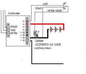
Here is what I came up with, quite simple and works very well, it uses a mechanical self latching relay and uses the discharge of the caps to close the relay
 

Attachments

  • E.S. share.jpg
    E.S. share.jpg
    13.8 KB · Views: 1,532
torqueon said:
Here is what I came up with, quite simple and works very well, it uses a mechanical self latching relay and uses the discharge of the caps to close the relay
Where's the resistor?
 
torqueon said:
The coil in the relay take's place of the resistor
That's interesting...

72ohms is not much resistance.

Does the line marked "red" always have voltage, or does that terminal on the controller get voltage only when the controller is energized?

What's the pack voltage?
 
Maybe it's not the resistance so much as the inductance of the coil, resisting the change in current just enough to prevent the massive influx to fill the caps?
 
What's the contact rating of that relay? What system voltage are you running?

I suspect the contacts may actually be closing before the caps are fully charged. If the voltage difference is low enough, it will probably be OK.

I was trying to come up with something like that only maybe a little fancier with a voltage comparator that waits until the voltages are close, then operates the relay.
 
You all asked contact rating, Opps the details not listed, I parelled two relay contacts for current; the coils are 2 x 12 volts serieied on 36 volt system. ( resister to make up 36 draw on 24 volt coils did not work ) Works well on 36 volts, hence a short and quick load no burn out!
How I came up with the plan is that i seriesed a 100 volt indicater bulb between batts and controller, it stayed lite better than a second on cap charge or dischage whatever ? , hell thats enough to pull in a relay. lacthing relay could work. Thus far has worked.
Humm how much is the contactor in relay is getting hit with the caps ?? have no way to really know. I tested with 24 starded gage with one stand for test no spark on contact.
All I can say is this seems to work
Only a bench test done by those who know will tell .
 
So the diagram is not exactly complete. That could be confusing...

If I understand correctly, two SPST relays are used: the closure-points are parallel to share large current, the coils are in series to double their resistance (140ohms total). One polarity (to the coils) opens the relays, the opposite polarity closes the relays.

Unless the line marked "red" is supplied only when the controller is on, the relays would stay energized when the switch is in the "Off" position.
 
Yes ! Sorry I omited the details was just trying to keep pic simple. In fact the switch can be a momentary switch

The large red is hot all the time, I am switching the negitive. Keep in mind the controller Negitive becomes positive when off, due to the caps. When on is negitive. So taking advantage of the controller negtive terminal going positive when off and negitive when on alows the use of the simple switch
 
Does it matter if I put the precharge resistor on the negative side? I was taught when connecting a battery positive then negative. And when removing a battery negative then postive.
 
It shouldn't matter which one it's in, it does the same thing either way.

In a two-wire connection, it also doesn't matter which wire you connect first, the current flows the same either way.

If you have more than one connection to something, like a battery with data connections, you'd want to connect positive *last* because you want the ground established first before connecting the data lines, to prevent any incorrect current paths and reference voltages.
Thxs. Make sense.
 
Back
Top