Precharge delay circuit

jonescg

100 MW
Joined
Aug 7, 2009
Messages
4,224
Location
Perth, Western Australia
Hi Guys,

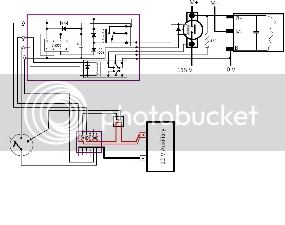
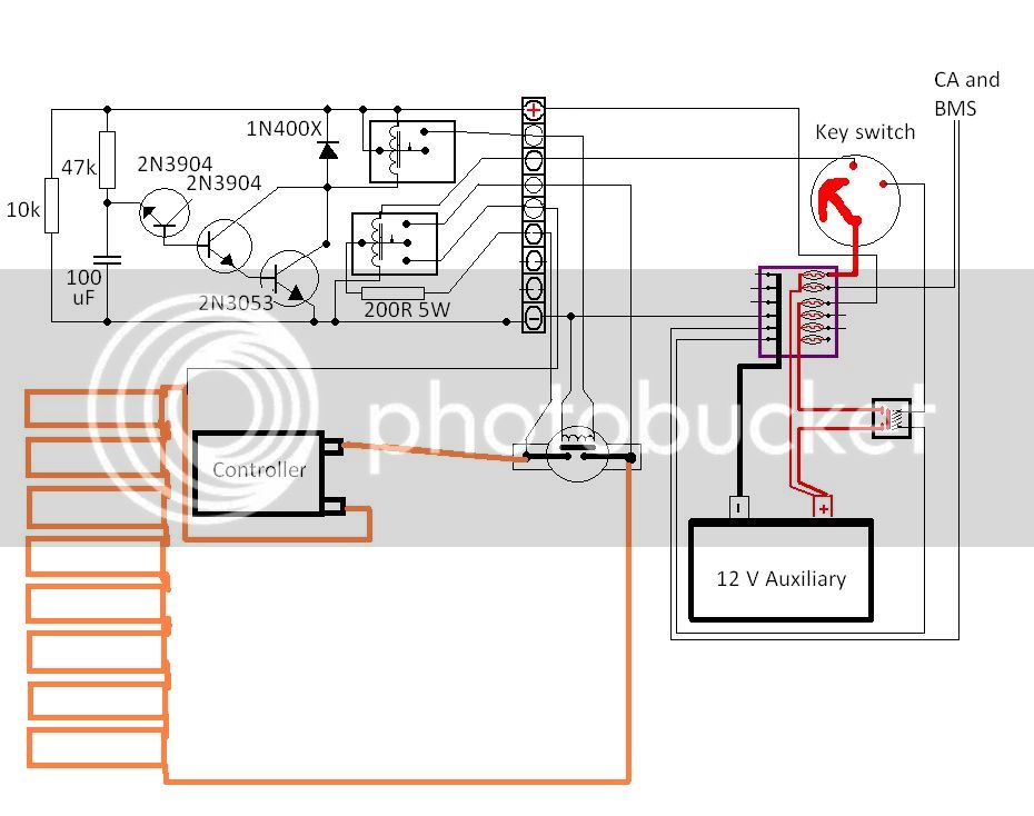
Can you please check something? The new TTXGP rules state that when the emergency stop button is hit, the high voltage system (i.e. the battery pack) should be completely isolated from the rest of the bike. Leaving a precharge resistor permanently wired across the main contactor terminals isn't good enough - it has to be disconnected too. So this means a N.O. relay will have to be used to close the precharge resistor circuit. Not sure what voltage these SPST relays are rated to, but 110 V might be pushing it, even with a big 200 ohm resistor.

I figure the first stop on my ignition key switch is good for this. BUT, how do I stop myself from belting right through to ON when the capacitors in the controller haven't charged up yet? I found a simple delay circuit which activates a SPST relay after about 7 seconds. I can then use the 12 V supplied to the delay circuit to run the main contactor circuit.

Finally, when the bike is switched off again, both the main contactor will go open circuit, and the precharge resistor circuit will go open circuit as I click right back to the OFF position. This leaves the capacitors in the controller still fully charged, but if I were to use the other pole of a SPST relay to run the same precharge resistor across the B+ and B- of the controller, it should discharge them.

Most importanly, can anyone see a glaring error in my schematic? Like 110 V worth of battery connection going through a tiny relay? Do you think the delay circuit will even work?

prechargedelay-1.jpg
CHRIS
 
Well I tried to build the delay circuit and it didn't work. Nothing new there, electronics and me don't really get along. However I figured I probably got the transistors around the wrong way so I pulled it apart and tried again. It seemed to fire the relay, but no delay (unless 0.05 seconds counts as a delay). So I don't know if I damaged a transistor in the first effort or not. Anyway, I was probing around with the + from the battery to check that the relay could be operated independently, and managed to touch something I shouldn't have. Now it doesn't work at all :lol:

Sigh. Is there some way of forcing a delay before going to full power on that doesn't involve kit electronics? Like a NOTC relay or something?
 
First, let's simplify, and work with just the delay transistor circuit. I've added red reference numbers for clarity of discussion.

prechargedelay-1a.jpg


What does R1 do? It appears to simply be a resistor from 12V to ground, which at 10Kohm will have a current passing thru it of 12mA, but other than being a tiny heater dissipating 14.4mW doesn't seem to be doing anything else in the circuit. (EDIT: I just realized R1 could be a bleeder resistor to discharge C1 when power is switched off.)

R2 and C1 I presume are giving you the delay. As C1 charges up, the voltage drop across it will become greater, and that across R2 smaller, as current decreases. At first, R2 is going to have 12V across it, and a current of 0.25mA. I am terrible at most math, but this calculator:
http://www.csgnetwork.com/rctimecalc2.html
shows it would reach about 1V across C1 in just over 4 tenths of a second. 2V at 0.85s, 3V at 1.3s, and so on.


However, I don't see how Q1 can be triggered, as it is not correctly in the circuit, so that it never gets the proper bias on it's base and so never turns on. If I understand correctly what you want to do, I think you are trying to use Q1 and Q2 as a darlington pair to provide lots of turn on current to Q3's base. If so, you need to connect the collectors of Q1 and Q2 together, to the 12V source (top of R2). Then connect the base of Q1 not to the base of Q2, but to the R2/C1 junction. Then the emitter of Q1 to the base of Q2.

I'd also put a small resistor between the R2/C1 junction and the base of Q1, to drop the voltage to the base after C1 reaches a certain point so it doesnt' overdrive the transistor (depending on it's max Vbe spec).

At that point, it will be set up so that once C1 reaches around 0.7V, around 0.28s after power on, it will trigger Q1 to turn on, which will then also turn on Q2, and the pair of them will turn on Q3, which will turn on RL1 relay, closing it's contacts (or opening them) and doing whatever it is you want the delay to do.

file.jpg


If I'm not understanding correctly, then help me figure out what it is you want it to do, and we can make it work like you want. :)

Once the delay works, we can figure out the rest of it.
 
Amberwolf - THANKYOU for replying!

Yes, the 10 k resistor was supposed to bleed the cap once it had completed it's job. I actually lifted the circuit from the web, so I didn't know what was right or not. Here it is here: http://www.circuitdb.com/circuits/id/92

The transistor the way it is drawn didn't make sense to me either. I figured the base needed a supply voltage in order to allow the emitter to do it's job, but being daft at electronics, I couldn't be sure.

How you have drawn it looks more likely to work. I will try it this weekend :)
 
The guy who did the circuit explains it like this:

The reverse connected emitter/base junction of a 2N3904 transistor is used as an 8 volt zener diode which creates a higher turn-on voltage for the Darlington connected transistor pair

although I'm not sure why he didn't just use a zener in the first place. :? Maybe he had a junk box full of those transistors.
 
Ah, that makes a lot of sense now, but yeah, a zener would be better. I didn't know a transistor could be used like that, but if I had, I probably would've used it that way, too. :lol:

@JonesCG: remember if you do it the way I drew it, it's going to activate the relay a LOT sooner than the way it was originally designed. So to get the original delay you will want to increase the size of C1.

You could also use a 555 timer to make it work; there are a bunch of existing circuit designs out there, even whole sites dedicated to the 555, like these:
http://home.cogeco.ca/~rpaisley4/LM555.html
http://www.555-timer-circuits.com/

This part contains power-on-delay circuits:
http://home.cogeco.ca/~rpaisley4/LM555.html#29
such as these:
LM555PowerDelay.GIF

I recommend the transistorised version, the third one down, and using the transistor to power the relay coil the same way your original circuit does. But you will probably only need the last largest transistor of your circuit.

If you want to try one of them, the 555 should be easy to get and very cheap. I have a bajillion of htem around here somewhere in surface mount--if you can work with that I can send you some in a little envelope if postage is cheap enough.
 
OK I found out from Fany what the capacitance of the KDH controller is - 4500 uF. Wit the help of this calculator:
http://hyperphysics.phy-astr.gsu.edu/hbase/electric/capchg.html
I worked out that if I have a 2000 ohm precharge resistor and a 110 V battery, I would have to wait 30 seconds before the caps were more than 95% charged.

Too slow. So I thought about dropping the resistor to 200 ohm, but this needs at least 60 W worth of resistor - not easy. So somewhere in the middle I can parallel the two 2000 ohm resistors and a 820 ohm resistor I have sitting around. This gives a final resistance of 450 ohms, and can handle a lot of heat. Based on the calculator I should have more than 95% charge in them by 6 seconds - much better!

Now, according to this calculator the maximum current in the circuit is ~0.25 A. If I use an off the shelf relay it should be able to handle these sorts of currents, even at 110 volts. I have a DPDT relay rated to 5 A, 30 V DC or 220 V AC. Do you think it will handle it?
 
Your resistor does not need to be very big if the load is not constant, I used 1W 200Ohm resistor for 1000uF 100V. It gets hot for instant but then caps are charged, heat is desipated and it cools down, it also melts hot glue around it every time. :D
 
OK so what better things to do on a day off than build a precharge delay circuit :)

prechargedelay.jpg


I have made the circuit covered in the upper purple box. The 555 timer circuit Amberwolf posted works perfectly, and the 47k resistor / 100 uF capacitor seems to give a good 6.5 seconds before enabling the SPST relay. Perfect :)

Now, the other relay I have installed is the 10 A / 30 VDC or 220 V AC relay with a diode across it. Being a DPDT relay, I can use both sets of poles to ensure a slightly longer lasting relay. It is going to experience 115 V DC, even though the currents should be well below one amp. This relay will be activated by the ACC position on the key switch. With a ton of high power resistors in parallel, I should be able to charge and discharge the controller caps in a good 5 seconds.

Will let you know how that works...
 
I hope not. As far as I can tell it says "must not be powered" That would mean a second contactor, and there's precious little real estate as there is.

Anyway, the delay circuit works nicely:

[youtube]dFYWeD67eW8[/youtube]
 
I believe the intent of this rule is for participants to use a manual switch/punch button as an emergency cutoff. This emergency cutoff should be in addition to your regular power switch (such as a contactor)

http://www.cloudelectric.com/category_s/513.htm

I think you may be spending a lot of time on something that would not be acceptable for the race. The whole purpose of the rule is to completely - and physically - isolate the batteries from everything else in case of a catastrophic electronic failure. Here, it appears that you are adding even more electronics which could potentially short out when things went bad......

While your setup might work, if I was a judge at the race I would not accept it as an acceptable substitution for a "standard" emergency cutoff switch.
 
The precharge delay circuit has nothing to do with the emergency cut-off. It's really for re-starting the bike. I have a big emergency stop button behind the seat which, when pressed, cuts power to the main contactor. The problem was that the precharge circuit was still supplying the controller with power, even though it was only a low supply. The controller still had charged caps that would give you a boot if you were stupid enough to go shoving your fingers deep into the bike.

Now I will set the emergency stop up to cut all 12 V power to the bike, thus shutting down the controller, closing the controller short and opening the main contactor.
 
Ahh... I see. So your cutoff dosen't actually cut the power from the main battery, it's cutting of the 12V charge used to activate the contactor?

Wouldn't it make better sense to put to cutoff directly off the main battery - I would have thought that's where it's supposed to go?
 
Never mind, I just looked up the rules that you'd mentioned. Zoiks -three cutoffs required?! :shock:


General circuit breaker – “Emergency Stop”
From eGrandPrix
Jump to: navigation, search
Three Emergency Stops are required as a stop has to be easily accessible both to the rider and to marshals, and must operate in the event of the rider being detached from the machine whilst underway.

I. The Emergency Stop is defined as a general circuit breaker which interrupts all electrical transmission between the accumulators and the energy consumers by means of a spark-proof circuit breaker.

When seated in a normal riding position, the rider must be capable of operating an emergency stop situated in front of him/her, without removing either hand from the handlebars. This breaker must be located in such a way that it is clearly visible and can also be readily operated by a person not sitting on the machine. This breaker must be clearly identified as such.

II. A second emergency stop must be provided which is operated by means of a lanyard attached to the rider. This must operate automatically in the event of the rider becoming detached from the motorcycle whilst underway.

III. A third emergency stop must be located behind the rider, and be positioned so that it can be operated if the machine is on one side following an incident. This must be operated by a red button, and identified with a yellow disc of at least 8 cm in diameter reading 'Emergency' in red or black letters. This button must latch down mechanically once it has been operated, and require manual operation to reset it.

The options suggested below are acceptable, as are other solutions that meet the stated requirements. The rider will be required to demonstrate the operation of the Emergency Stops during Technical Control.

1. A low voltage switch (e.g. push button) as a control for a contactor relay in which the contactor can be mounted down near the motor and keep the power voltages and currents away from the rider and top side of the bike.
2. A relay with an integrated “breaker” switch, which requires running the full battery voltage to wherever this breaker is mounted. Operation of the general circuit breaker must also isolate any pre-charge resistors, if installed.
In order to prevent contact melting of the general circuit breaker its ampere squared seconds characteristics, representing heat energy dissipated on the breaker contacts during switching, must be sufficient to guarantee proper operation of the circuit breaker, even under surge current conditions, in particular those occurring during the connection of the accumulator to the power plug.

Low power accumulators provided for low voltage circuits, for example auxiliary circuits, do not have to be isolated by the general circuit breaker and Emergency Stops, provided that they are completely isolated from the main power accumulators.

Retrieved from "http://www.egrandprix.com/wiki/index.php?title=General_circuit_breaker_%E2%80%93_%E2%80%9CEmergency_Stop%E2%80%9D"
 
I dread to think how big the knife switch would need to be to manually kill the battery supply :shock:

Thankfully in the updated rules you don't need to have a lanyard. When I took a couple of spills at Wakefield Park, the lanyard never popped and it actually dragged me with the bike :shock: :shock:
 
Well, that's certainly good news about the laynard.

For your pre-charge problem: Couldn't you use something like a multi-position On-On-Off switch? Position three, all off. Position two, activates the pre-charge circuit, then position one activates the main contactor. It would be purely manual, and you'd have to wait a bit for the precharge to take place. But it would certainly simplify things.

http://search.digikey.com/us/en/products/VGD2GHNB-AAC00-000/432-1090-ND/483662

VGD2GHNB-AAC00-000_sml.jpg


http://search.digikey.com/us/en/products/084830%2007/700-1002-ND/1650949

084830%2007_sml.jpg
 
That's precisely what I've drawn on the wiring diagram ;)
 
Back
Top