Sancho's Horse
1 kW
“By three methods we may learn wisdom: first, by reflection, which is noblest; second, by imitation, which is easiest; and third, by experience, which is the most bitter.” Confucius
I am preparing to head down the bitter road again. So, this is my prelude to oil cooling a hub motor.
My thoughts:
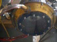
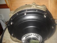
My need for low-end torque in stop and go situations means there will be lots of heat being developed. The motor I have is a nine continents 3000W hub motor.
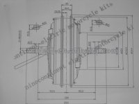
I am not an engineer, nor do I have access to tooling (other than a drill press, angle grinder, metal cutoff saw, a jig saw *not currently working, a dremel, bench vice, and files). I have been working through lots of calculations, because I am using a nuvinci N171 (developers kit), and am not at the edge of the envelope, but close enough it is worth keeping tabs.
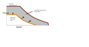
Torque, Power, and Speed Limits* of nuvinci N171
Maximum Sustained (Pulse-free) Input Torque 65 Nm (48 lb-ft)
Maximum Instantaneous (Spike) Input Torque 130 Nm (96 lb-ft)
Maximum Sustained Input Power 5 kW (7 hp)**
Maximum Recommended CVP Speed Input: 1000 RPM / Output: 1000 RPM
The motor is set-up for 700RPM no load. It has 3 speed (80%, 100%, 120%) switching. It also has ebrake.
Now....Here are my thoughts on cooling.
I am a big fan of drilled, centrifugal, internally finned air cooling methods. They are relatively easy, and they work. And...I think someone else has pointed out, no matter what cooling method you use (air, water, oil) you are ultimately using air, because in all three the final energy sink is the atmosphere. Other oil cooling attempts have met with various levels of success, ranging from failure to pretty good.
I have reported elsewhere, self-fan cooling vs. liquid cooling showed liquid cooling arrives at 2-3 times the level of Amps per mm^2. This requires a pump and radiator to get anywhere near these levels of difference. Most approaches to oil cooling currently modded use the oil to move the heat from internals (windings, etc.) to the cover more efficiently than with air, due to the huge difference in thermal conductivity between air (0.0243 W/mK @ 25C...0.0299 @80C) and oil (>0.138 @25C). Water has better thermal conductivity (0.06W/mK @25C) but will still have an air gap from the electronics, decreasing its effectiveness, and will require a heavier apparatus/tubing/channelling to make exchange. Oil can go right on the electronics (with some modifications).
Now, I brought up, and I am sure others have as well, the covers just do not provide the level of surface area required to really achieve the levels of cooling. I saw b0b did a pretty cool mod using aluminum radiator fin on crossbreak's Converting a hubmotor to middrive thread: http://endless-sphere.com/forums/viewtopic.php?f=28&t=45245&start=135
I like it, but I think there is far greater possibility for passive oil cooling hubmotor design.
So...without further word interruptions, here is how I intend to oil cool my motor.
First, I am going to do testing to establish unaltered motor temps.
Next, I am going to use common, readily available pipe elbows with flare nuts, and clear tubing to establish oil movements out of and back into the hub motor during spin up/ebraking using a mounting device I have created and a video camera I call the Nam cam.
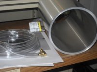
Finally, I will put a series of elbows and flare nuts at intervals around the hub, with aluminum tubing traversing the space in between spoke flanges, with a prepared patterned laminate of aluminum flashing housing and intimately in contact with the tubing.
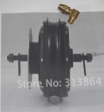
My feeling is that centrifugal cooling goes both ways. I hope to show that using it with oil cooling and a radiator of much greater surface areas housed in the space between the spokes is a big win for cooling, and a proposal which will give oil cooling its due.
Feel free to chime in.
I am preparing to head down the bitter road again. So, this is my prelude to oil cooling a hub motor.
My thoughts:
My need for low-end torque in stop and go situations means there will be lots of heat being developed. The motor I have is a nine continents 3000W hub motor.

I am not an engineer, nor do I have access to tooling (other than a drill press, angle grinder, metal cutoff saw, a jig saw *not currently working, a dremel, bench vice, and files). I have been working through lots of calculations, because I am using a nuvinci N171 (developers kit), and am not at the edge of the envelope, but close enough it is worth keeping tabs.
Torque, Power, and Speed Limits* of nuvinci N171
Maximum Sustained (Pulse-free) Input Torque 65 Nm (48 lb-ft)
Maximum Instantaneous (Spike) Input Torque 130 Nm (96 lb-ft)
Maximum Sustained Input Power 5 kW (7 hp)**
Maximum Recommended CVP Speed Input: 1000 RPM / Output: 1000 RPM
The motor is set-up for 700RPM no load. It has 3 speed (80%, 100%, 120%) switching. It also has ebrake.
Now....Here are my thoughts on cooling.
I am a big fan of drilled, centrifugal, internally finned air cooling methods. They are relatively easy, and they work. And...I think someone else has pointed out, no matter what cooling method you use (air, water, oil) you are ultimately using air, because in all three the final energy sink is the atmosphere. Other oil cooling attempts have met with various levels of success, ranging from failure to pretty good.
I have reported elsewhere, self-fan cooling vs. liquid cooling showed liquid cooling arrives at 2-3 times the level of Amps per mm^2. This requires a pump and radiator to get anywhere near these levels of difference. Most approaches to oil cooling currently modded use the oil to move the heat from internals (windings, etc.) to the cover more efficiently than with air, due to the huge difference in thermal conductivity between air (0.0243 W/mK @ 25C...0.0299 @80C) and oil (>0.138 @25C). Water has better thermal conductivity (0.06W/mK @25C) but will still have an air gap from the electronics, decreasing its effectiveness, and will require a heavier apparatus/tubing/channelling to make exchange. Oil can go right on the electronics (with some modifications).
Now, I brought up, and I am sure others have as well, the covers just do not provide the level of surface area required to really achieve the levels of cooling. I saw b0b did a pretty cool mod using aluminum radiator fin on crossbreak's Converting a hubmotor to middrive thread: http://endless-sphere.com/forums/viewtopic.php?f=28&t=45245&start=135
I like it, but I think there is far greater possibility for passive oil cooling hubmotor design.
So...without further word interruptions, here is how I intend to oil cool my motor.
First, I am going to do testing to establish unaltered motor temps.
Next, I am going to use common, readily available pipe elbows with flare nuts, and clear tubing to establish oil movements out of and back into the hub motor during spin up/ebraking using a mounting device I have created and a video camera I call the Nam cam.

Finally, I will put a series of elbows and flare nuts at intervals around the hub, with aluminum tubing traversing the space in between spoke flanges, with a prepared patterned laminate of aluminum flashing housing and intimately in contact with the tubing.

My feeling is that centrifugal cooling goes both ways. I hope to show that using it with oil cooling and a radiator of much greater surface areas housed in the space between the spokes is a big win for cooling, and a proposal which will give oil cooling its due.
Feel free to chime in.


