PWD's Rocky Mountain Element - 2WD

goatman said:
100amp from 7p is 14a/cell, whats the volt sag?

im planning 60amp from 4p or 15a/cell max burst

I'm pulling 110A peak which is actually ~15.7A per cell. My pack resistance is about 47 milli-ohms so it sags about 5.17V at peak. Ambient Temperature around 25 C.
 
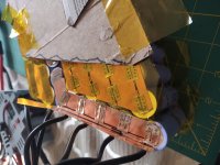
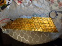
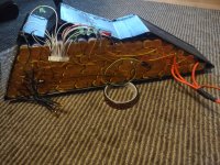
The new battery pack seems to be working well, even on our hottest week (so far), the BMS and two temp sensors (sitting on top the nickle strip) only went a few degrees above ambient.

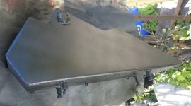
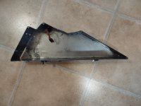
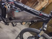
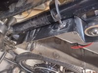
I decided to paint the battery box to hold the rust back. I applied some seam sealer (like rubber caulking but for metal) and gave it a few quick coats of primer and satin black.
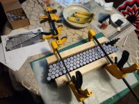
IMG_20200604_095707.jpg

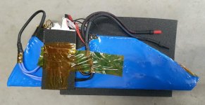
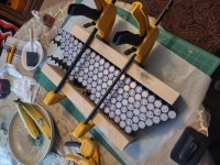
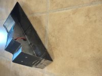
Here is a shot of the pack out of the bike:
IMG_20200604_095745.jpg
 
I am having a slight issue with the motor temp gauge reading "sagging" or "dropping" when I really hammer the throttle. For example lets say I hit hit open throttle and am pulling peak current from my pack, the temp gauge will appear drop around 15%. When I let off the throttle, the temp reading jumps back up.

The temp guage is powered by a DC to DC board (pack voltage to 13.4 VDC) (positive and negative wire) and the 10K NTC thermister signal (one wire) is coming from the motor.

Any ideas? :?:
 
Perhaps there is some interference from the phase cables but I would guess others would have a similar issue with any hub motor w/ a temp sensor. So far, I haven't been able to find a case like that. Unfortunately, I don't have a great electrical knowledge to know if that is even a factor.
 
Thank you, that is an interesting problem and may be related to the issue I'm having with the temp reading. I'll have to do some troubleshooting.
 
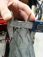
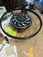
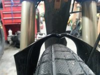
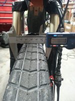
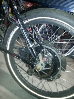
I've been out riding the bike (mostly) daily and it is performing well. The side offset (approximately 7mm) of the front tire was bugging me a bit and I had been itching for a wider front tire/rim as well. I had ordered a 26 x 2.4 Schwalbe SuperMoto-X to replace my 26 x 2.0 Schwalbe Marathon. The new rim I chose is the Alex DM24 26" (from ebikes.ca). The spokes are Sapim (from ebikes.ca). I used the ebikes.ca spoke calculator and it worked out perfectly! Here is a shot of the offset tire before:

IMG_20200610_110905.jpg
IMG_20200610_111007.jpg

Lacing the new rim:
IMG_20200610_133622.jpg

Old bike as truing stand:
IMG_20200610_165437.jpg

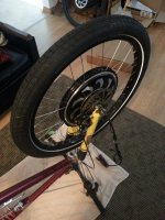
Here is the new tire/rim on the bike.:
IMG_20200610_183445.jpg
IMG_20200610_183842.jpg

I am pretty happy with the result. I could have went with an 8mm offset vs 7mm but I can re-adjust in the future. The spokes and spoke nipples from Grin were easy to work with vs the cheaper ones I'm used to with pre-laced hub-motor kits. I'll be doing the lacing for my self from now on.
 
Let us know how you like it. I have the same tire in 20" form, also with an alex DM24 on the front of my recumbent bike. It's nice on the pavement, but most of the trails around me are sandy gravel, and I'm about to try a Smart Sam as a second wheel to swap to. I also have a wider wheel to try, since the Super Moto-X is much wider than the rim. Lacing your own wheels feels great, doesn't it?

ACtC-3dm_JnYspygeq451jEC_bLZD24jBTTi1F24qO0fIFyJdcqI2-bHOzJAOX7IO6jAJtiwqhdi_Isi94FN82nR9AaDdIl--Pwt5pFhMv0a30L7lHVyCmRWJGRg5zj5C_jL40DzmIkwZbGAXOB3bbR99zEu=w4160-h2340-no
 
The SuperMoto-X tire is working great and it noticeably taller than the previous tire I was running; which is good. Very happy. The tread pattern appears very similar to the Big Ben Plus which I'm running on the rear.

In other news; I had damaged my BMS (heavy rain, not sealed) a while back and have been running a new one. The repair to the old one only worked for a few hours; I thought I was in the clear. Call me crazy but the new BMS (ANT BMS 320A - same as the old) appears to perform better! I'm not sure if it is because it is using different mosfets or what but my voltage sag seems less than before. That is a nice silver lining.

I have since turned up the max battery amps on the rear controller from 85A to 115A and the difference is noticeable although with diminishing returns. My battery pack is now delivering peaks of 7kw. I estimate my actually peak power output of the bike is somewhere around 4.6 kw. I've added a small 60 x 25 48V fan for fun:
IMG_20200722_105941.jpg

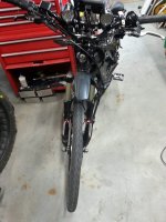
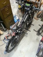
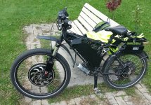
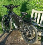
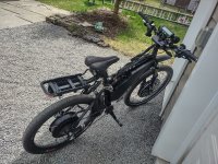
Recent shot of the bike:
IMG_20200722_105924.jpg
 
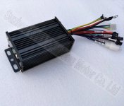
I've completed a new front controller upgrade to the bike this week. I ordered this simulated sine-wave controller a couple of months ago:
https://www.aliexpress.com/item/32959235022.html
HTB1RZuvX.vrK1RjSszfq6xJNVXaT.jpg

The goal was to (finally) replace my Magic Pie 4 internal controller. Although the controller still worked; it wasn't able to be programmed anymore and it had some glitches that I wanted to eliminate. The glitches were:

abrupt accelleration from start. Even with acceleration turned down it felt jerky.

regen wouldn't work unless I was below 56.5V; not ideal since I pretty much always top up my pack right before riding. I rely heavily on regen braking force on the front and rear.

when I exceeded the Magic Pie's max rpm, it was if regen braking would suddenly engage unless I disabled it's throttle signal to the controller

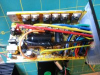
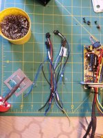
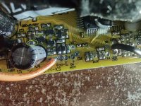
When the new controller arrived, I was uncertain if it was in fact, a programmable Infineon 4 clone/xie chang controller like I was hoping for. I opened it up and had a look. It seems promising as the board looked similar to other Infineon 4 style controllers I've seen online. The board says "606-THP-5" which is a good indicator that is actually a KH6XX type controller. I added some leads to the +5, GND, SDA, RXD and TXD spots on the board.
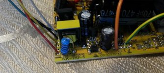
IMG_20200901_141129.jpg

Once I figured out the correct wiring to the USB-to-Serial adapter as seen here
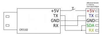
vrrxt9_thumb.jpeg

I was able to successfully program it using the XPD controller software! After soldering the matching motor and throttle/brake connectors (re-used the magic pie waterproof connector) I gave the motor a test spin. The motor phase cable and hall sensor wires matched colour for colour with the controller (a nice bonus :mrgreen: ).

After a few trial runs; I figured out that I needed to jump the BK to GND on the board to enable regen even though I had enabled it in the firmware. I was also able to get the motor rpms to "130%" which is right around what I was hoping for. This is probably like a phase advance, basically the poor man's flux weakening. This allows the front motor to help the rear motor out as it nears max rpm. Not a bad feature set for a $60 USD controller in my opinion. I would have went with a Greentime or KT controller but they do not seem to have this ability.

removing the original controller and running a new controller wire harness to outside the hub motor
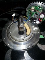
IMG_20200902_093158.jpg

BK jumped to GND to enable regen:
IMG_20200903_160948.jpg


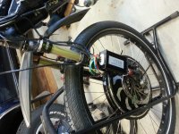
After having the bike out for a couple shakedown tests; I'm very happy with the new controller. The acceleration is much smoother and all my glitches are gone. I'm keeping the controller at 25A battery 75A phase which is pretty much the same setting as the original magic pie 4 controller although it feels like it has a bit more punch. The bike is working like a dream now.
IMG_20200904_124356.jpg
 
The bike has been working well and is more enjoyable without the kinks of the old front controller. Shorty after I installed the front controller; I trimmed out all the un-used cables for a cleaner look.
IMG_20200904_151514.jpg

I've sealed up the top where the cables exist with black liquid tape for a good from far appearance. It's definitely more weather resistant now and the front controller blends in enough for my needs.

IMG_20200919_142749.jpg

I'm considering grinding down the magic pie shells and paining them black over the winter. That will be after a fork and rear shock maintenance.
 
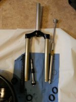
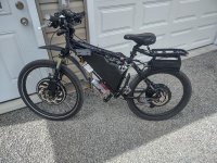
After doing some maintenance over the winter to the bike, I've been back on the road for a few weeks. I replaced the seals on my rear shock (Fox Float R), serviced my single coil fork (Marzocchi Bomber MX Lo), changed/bled the fluid on front brake (Avid Juicy Three) and modified my steel battery box so that the shock linkage doesn't make contact.
IMG_20210131_130956.jpg

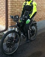
I have also made the switch to wearing full moto gear for some protection (now using different gloves than in the photo).
IMG_20210413_184940.jpg

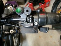
The chainring was rubbing on the derailleur (I must have bent the ring a bit) so I've fixed that which involved removing the battery and battery box to access the derailleur mount. I just finished relocating my turn signal switch to below the throttle vs above the throttle which will hopefully make it a bit easier to operate while riding.
IMG_20210501_115445.jpg

Overall pretty content with the bike and performance. My battery pack isn't quite a year old yet but for my next one (maybe in a couple years), I'll definitely be going with higher voltage and less current.
 
The rear Big Ben Plus tire was looking pretty worn and I really wanted to try something a bit wider. I strongly considered motorcycle/moped tires but didn't want to go down that route. I was hoping I could have found a moto tire that fits a 24inch bike rim but 20 inch motorcycles are few and far between and quite expensive. I didn't want to lace the motor on a different rim either. I went with the tried and true Maxxis Hookworm (24" x 2.5") and it was worth it. I was concerned that it might not be as puncture proof as the Big Ben Plus but it seems to be working well.

On the front, I notice that the rear tire was still off center a bit even though I relaced the motor to a new rim with spoke length made to offset to one side. After about 45 minutes of adjusting the spokes (they are pretty much at the limit), I managed to get the tire perfectly (within 1mm) centered and trued. Job done.

I just realized I had a 10mL syringe of Statorade sitting in my parts bin and though I'd add some more to the rear motor to help combat the waste heat. I didn't want to remove the rear hub again so I opted for the "hole in the side cover" method to add more Statorade. I used a small bit of tape around a drill bit to act as a drill stop on a 1/8" bit. While drilling, I made sure to clean out the bit as I went and had a shop vacuum going to help keep the shavings out of the motor.

I added around 4mL (I think I added around 8mL originally) and a piece of tape over the hole and went for a ride. No extra resistance noticed. Ah ha! The motor cools down noticeably faster now, even though I already had some Statorade inside. What an easy improvement.

IMG_20210605_193701.jpg
 
I'm beginning to plan next year's upgrades to the bike. :bolt: This will end up pushing to bike further away from it's bicycle roots as I will have to get rid of my front derailleur and 7 speed freewheel. The upgrades include:

20S6P 21700 cell pack - I want more top end and a longer power curve; for both motors. This will require some fairly precise modifications to my battery box to be able to cram another 22 21700 cells inside - I will probably go with Molicel P42As.

205 45H motor - my 205 35H leafbike motor is fantastic but when I switch to a higher voltage; I will be pushing max power for longer durations and I don't want to heat up the motor even more than it already is

72V front controller - my current front controller is good for up to 60V - rear controller will stay for now

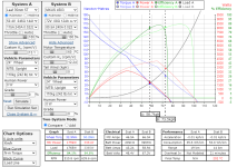
New power curve for the rear motor will look something like this:
bikeupgrades.png


Some questions I have:

Are there any other choices for a 205 45H motor besides the MXUS 3k turbo / XFO 45H? I need something that fits dropouts no wider than 142MM like the MXUS 3k.

What would it take to modify my small 6FET Xie-Chang controller to work on a 72V system? Is it just a matter of replacing the capacitors and mosfets with higher voltage ones?
 
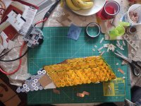
The Samsung 40T's (were cheaper than Molicel P42As at the time of purchase) have all been tested and sorted. Now the assembly begins:
IMG_20220331_085144297.jpg

The bottom half of this pack is LONG (521mm) not including padding. It is going to be the tightest fitting, most complicated, largest pack I've built so far.
 
The battery pack is slowly coming together.
IMG_20220401_081934085_HDR.jpg

It will need to fit in my modified battery box:
IMG_20220401_082028547.jpg
IMG_20220401_082018772.jpg

I have to grind down the plastic cell holders to get the pack to fit and I need to make sure a layer of rubber can fit on the bottom of the pack for some cushion. My last pack had rubber all the way around but this one is a lot tighter. I'm also removing excess glue etc.. before starting the spot welding.

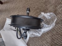
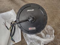
A new motor has arrived (ordered from MXUS on Alibaba) but I don't plan on playing with it until the new pack is up and running:
IMG_20220404_141846972_HDR.jpg
IMG_20220404_141833648_HDR.jpg
 
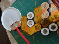
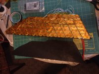
Spot welding going fairly well - had to add a second lipo in paralell to have enough current to weld through 0.15 Nickle plated steel and 0.15 mm copper sheet.
IMG_20220410_094220828.jpg

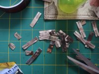
realized I didn't have enough Nickle plated steel strips (seller sent me half of what I actually ordered. I had to make sure with 0.2mm pure nickle and cut my own slots - didn't weld as easy or as well but did the job
IMG_20220410_094228180.jpg

positive end terminations
IMG_20220412_141854754.jpg

IMG_20220412_141843714.jpg
negative end termination
IMG_20220412_084911829.jpg
IMG_20220412_084906753.jpg

spot welding complete
IMG_20220414_093127977_HDR.jpg
IMG_20220413_192106204.jpg

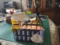
Very tight fit into the batter enclosure + all balance leads wired in
IMG_20220413_192715802.jpg

battery box test fitted
IMG_20220415_143350527_HDR.jpg

new shaft collar mounts added - no hardware protruding into the box
IMG_20220415_143359242_HDR.jpg
 
On other fronts for this bike, I've had to acquire a new DC to DC converter for my 12V lights etc... I ordered one but it was not adjustable so changed out a resistor for a variable one so the output voltage can be adjusted (I like mine at around ~14.3V). Had to buy from amazon, since I wanted it soon rather than later.
https://www.amazon.ca/gp/product/B07WXG8RLP/ref=ppx_yo_dt_b_asin_title_o00_s00?ie=UTF8&psc=1

I've detailed how I adjusted the output here (shout out to scianiac and amberwolf):
https://endless-sphere.com/forums/viewtopic.php?f=2&t=115846&p=1712122#p1712122


Also, my front KH606 Xie chang controller was not setup for 72V. It was only advertised as 48V/52V. Luckily all the components inside can handle 72V. Regen was not working above 77.6V however. I spent hours trying to find out how to change this limit. Although the controller was programmable; the max regen voltage that could be set was 77.6V

Thanks to amberwolf and his guidance, I've learned how to troubleshoot and reverse engineer boards a little better. Enough so I was able to figure out how to modify the max regen voltage on this controller which I've documented in this thread:
https://endless-sphere.com/forums/viewtopic.php?f=2&t=23745&p=1712191#p1711598

I couldn't find any relevant info; so I had to figure it out

Also note - those resistors are tiny. I had to use magnifying glasses etc... and felt like the dad from honey I shrunk the kids
IMG_20220423_082217564_HDR.jpg
 
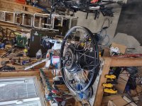
I've been working on the new motor now that the battery pack is up and running. The performance is great already; but I wanted to cram some more copper in the rear wheel. I laced the 45mm motor into an Alex DM 24 24" rim with Sapim strong sokes from ebikes.ca

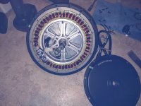
Opened up the hub to seal the covers and add some Statorade. The windings seem a tad on the sloppy side but functional.
IMG_20220425_182426146.jpg

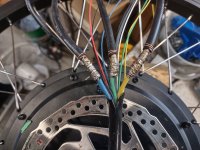
Chopped the phase cables as they exited to motor so I could add on some 8AWG.
IMG_20220503_091424196_HDR.jpg
IMG_20220503_095400713_HDR.jpg

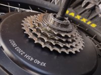
This motor was difficult to fit in the bike's dropouts... I really had to wedge it in there. The bikes dropouts are ~135mm and this motor's axle shoulders are ~142mm plus a couple of washers. I chopped up an unused DNP 8 speed freewheel I had in my parts bin. The way the cogs are fitted to the freewheel allowed me to use four cogs. I could have maybe fit 6; but they are secured in groups. I degreased and cleaned as much as a could.
IMG_20220503_154841295_HDR.jpg
 
Thanks! I used a Weller 80W iron with a big fat tip: https://www.amazon.ca/Weller-SP80NUS-Heavy-Soldering-Black/dp/B00B3SG796
The iron itself isn't very good, the tip seems to be wearing out after a few years (maybe a few hours total use) and there is no temperate control but it gets the job done.

I splayed out the high strand 8WG cable and put the motor phase cable in the middle and wrapped with with some solid 22awg copper wire. Before starting the soldering I applied some flux paste and then hit it with the iron and some rosin core 60/40 solder. I had the iron on the cable for quite a while I spooled out the solder until the cables were "full".
 
The new 45mm motor is installed and has been working great. The first few rides were a bit intimidating with that extra thrust on the rear wheel. This thing is a rocket when it takes off. I think I'm going to add more Statorade (it curranty has 10ml) later on but overall the motor is staying cooler than my leaf 35mm.

IMG_20220510_123407128_HDR.jpg

IMG_20220510_123348840_HDR.jpg
 
Must be a blast, and glad to see your new battery pack up and running!

I considered building the new battery for my recumbent as a 20s15p and doing dual motors, but my goals of long distances with pedaling kept me to 14s21p instead. I'd rather make a power build out of an upright bike with full suspension like yours anyways for going up hills offroad.
 
Back
Top