Well, they provide incomplete and conflicting information in all of that, including at least one impossible statement given the hardware involved. Not surprising, as that's the norm for information supplied by sellers (when they supply any at all).

I myself wouldn't feel safe at all with that device, and because the info provided doesn't even match itself, wouldn't trust that it does any of the functions it claims to, including even the diode protection, without reverse-engineering it completely (given it claims an MCU in there, if there is one, I wouldn't be able to really tell for sure how it's software worked and so couldn't trust it's functions to operate as designed).
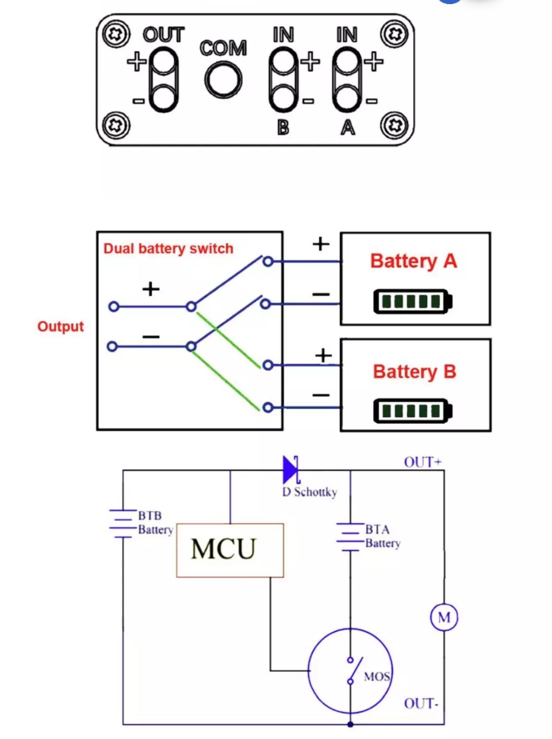
For instance, the last picture, the schematic, must be incomplete (I hope). If it's not incomplete, then it doesn't work as described, and doesn't protect the way you probably want it to.
It shows only one schottky, oriented so that it always allows power from battery B to flow into battery A. (BTA, BTB).
However, it would always prevent power from BTA from flowing into BTB.
The MOS (FET) switch also can only cut off BTA from the output, it cannot cutoff BTB.
So BTB would, despite being named B, be the primary battery of the system, since it cannot be disconnected no matter what.
The switch diagram above the schematic shows that it disconnects or connects both the + and - of one of the batteries to the output, which is not how the schematic shows things working. A switch designed the way the diagram shows will also only connect one battery at a time, and never connect both. It only switches between them. If they are just using their own schematic methods instead of standard ones, then the switch could do anything at all and we have no way of knowing what that is. It could even connect just the + of one pack and hte - of the other, which would not provide any power to the output at all. Or it could connect the plus and minus of the same pack together and cause a fire. Etc. Literally no way to know what they intend by that diagram if it is not a standard method of showing it...and if it is the standard....it doesnt' do what the other stuff says it does).
So it must be (hopefully) for a different module than the schematic is. They can't both be for the same device. And the description below that doesnt' match how either of the diagrams work.
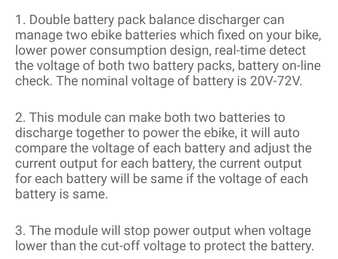
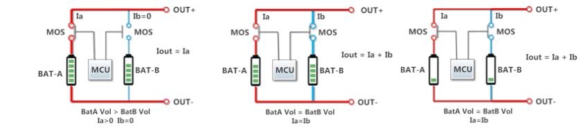
The first statement in paragraph 2 conflicts with the switching diagram; it can't make both of them discharge together.
The statement "and adjust the current output for each battery" is not possible without much more circuitry than this module could hold--it would need to have a complete independent DC-DC converter, that has a current-limiting output, adjustable by the MCU, for each battery, to actually adjust the current output.
The last statement in the same paragraph is sort of true--if each battery is identical in characteristics including complete internal resistance, then yes, at the same voltage the current would be divided equally between the two...but that's almost never the case, and is not the case for two entirely different batteries such as you have.
The last paragraph, 3, means that if you set it up to stop discharging to protect the 52v pack, you will not be able to use much of the 48v pack. If you set it up to protect the 48v pack, then the 52v pack will be completely drained first, until it's own BMS LVC kicks in and turns it's output off. However, if the schematic is correct, it can never disconnect BTB regardless of how low it's voltage gets.
Can they also send you the program to read and write settings and data to the unit? And tell you what kind of cable it takes to do this (do they sell the cable?) If not, that part of the unit is useless to you, unless you can "sniff" the data stream (assuming it just always outputs this and doesn't have to be commanded to do so) and reverse engineer what the data means, then write a program and build hardware to display the voltages (or write a program to send the data over BT to a phone, etc, and an app for the phone to display them). Still wouldn't let you program it, but you'd have made a complex dual multimeter out of it.
Regarding using Nanos...I have as yet learned very little in my projects, don't yet know enough to program one. I recommend http://arduino.cc as a good source of info and other people's projects to dive into, however, if you already know how to program them. You could find pieces of others' projects that do things you want to do, and copy those code bits into your code to save time writing it, for instance.