I've finished rebuilding the battery pack from a Currie iZip Ultra (2011 model).
The canonical posts are here:
Part 1: http://syonyk.blogspot.com/2015/05/izip-ultra-2011-battery-pack-teardown-1.html
Part 2: http://syonyk.blogspot.com/2015/05/izip-ultra-2011-battery-pack-rebuild-2.html
Part 3: http://syonyk.blogspot.com/2015/05/izip-ultra-pack-rebuild-33.html
But, for ES, I'll copy/paste them here.")
Warning. Long.
===================================================
iZip Ultra 2011 Battery Pack Teardown 1/3
2011 iZip Ultra Battery Pack Rebuild
Someone at work was getting rid of an ebike they were sick of. It didn't work. One of my flaws is that I'm a sucker for free stuff I'm interested in, especially if it originally sold for a lot of money. Please ignore the stack of phones and tablets on my desk that I need to fix or strip for parts...
A quick trip to pick it up, and I had the following sitting in my garage:
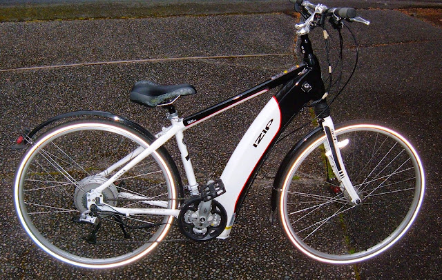
It's a 2011 Currie iZip Ultra. This is a 500W geared rear hub motor, pedal assist ebike, with a 36v, 10AH pack. Of note are the very small, high pressure tires - it's supposedly quite efficient as far as power use goes, even on a higher assist setting.
Unfortunately, this one wasn't going to do any assisting at all. The battery pack was stone dead. I got a back story involving the charger, a power outage, and the pack dying, so perhaps the charger drained it after the power outage, but whatever the case, it was dead. Really, really dead.
The bike uses lithium cells - ICR (LiCoO2) cells to be specific. Lithium cells are great in terms of power density and energy density, but they require some specialized care and feeding. They must exist in a voltage range between about 2.7 and 4.3 volts per cell (and spend most of their life in the upper 3v region).
Discharging a lithium cell below 2.7 volts tends to do physical damage to the cell if it's left there (and, really, you shouldn't ever have them below 3v/cell for any length of time). Skipping to the punch line, this is a 10S pack. That means the pack should live between 30v and 43v. Maybe down to 27v, briefly.
10 volts for the whole pack is right out. That's "bad." That voltage, combined with the time sitting, means the pack is physically damaged, recharging the batteries is not a good idea, and even if it will take a charge, it's very likely significantly short on capacity. Individual cells were between about 0.6v and 1.2v. Neither is 2.7v or greater...
A replacement OEM pack is $600. A bit of research indicates that I can do a lot better. So, of course, I tried to.
This teardown was done against the best advice of warning stickers, totally voiding any remaining warranty on the pack (not that there was one 4 years later), and is definitely not a good idea. So, of course, I continued. iZip had nothing to do with this teardown and isn't responsible for any of the stuff I did to their pack.
Full Pack Overview
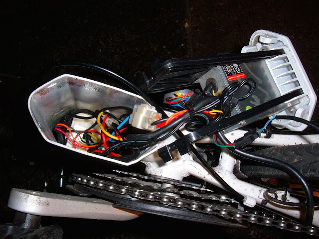
The pack lives in the thick frame tube, arching up from the pedals to the steering bearings. It's surprisingly easy to remove, though - remove a few screws, the bottom of the tube (containing the controller) drops out, and the pack follows quickly. It looks sort of like a banana.
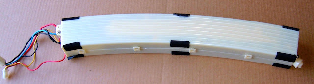
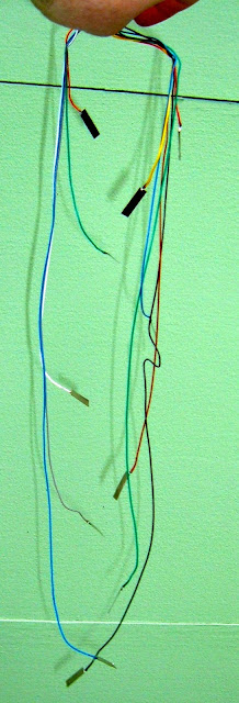
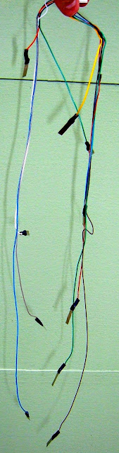
There are two three-pin connectors coming off the pack to disconnect before removing it. One (the triangular connector with thicker wires) goes to the motor controller. The other (thinner wires) connects via a cable to the external charging port up higher on the tube.
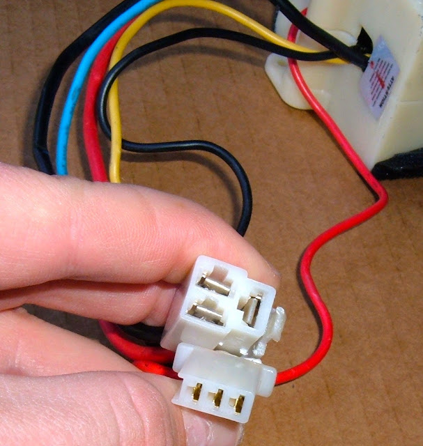
The black and red wires on the "triangle" plug are power and ground. I'm not entirely sure yet what the blue wire is, but I believe based on some conversations with iZip that it's a voltage sense wire (it just happens to be a lot larger than needed).
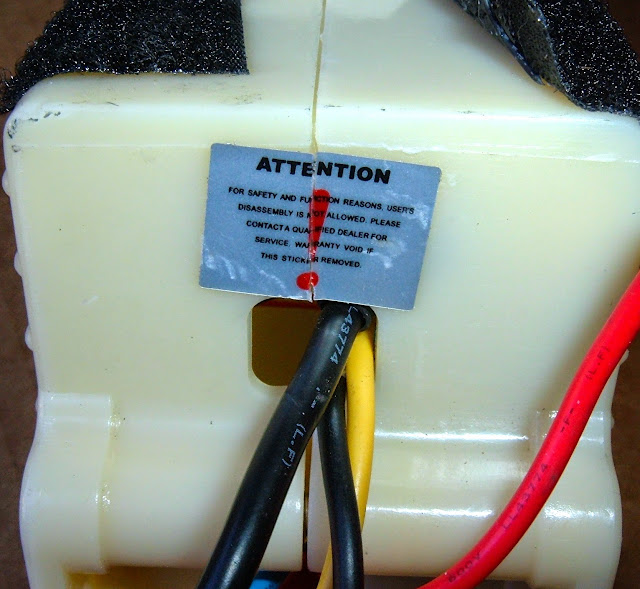
A close inspection of the end of the pack indicates that I'm going to void the warranty if I remove the sticker. Fortunately, the sticker is still there - just sliced! I should note here that the previous owner did pop the pack open when it died, so I'm not the first to be in here.
"For safety and function reasons, user's disassembly is not allowed. Please contact a qualified dealer for service. Warranty void if this sticker removed."
Well... the warranty is void anyway. According to the information that came with the bike, the warranty for the battery is "Lithium-ion type: One year (12 months) from purchase date by original owner. Warranty is void in the event proper care instructions as per the owner’s manual are not followed." One year warranty? This is why I like LiFePO4... Also, I'm reasonably confident fully draining the pack is not proper care. It doesn't matter anyway as it's a 4 year old bike.
Two bolts and a bunch of snaps hold the shell together. Remove them, and in we go!
Pack Insides
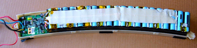
The first view we get with the shell off is the BMS (Battery Management System), some padding tape and a whole lot of batteries. As this is a battery pack, that's a good thing. The cells are 18650s, which is great - they're a standard size and easy to obtain.
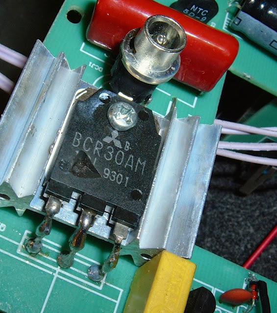
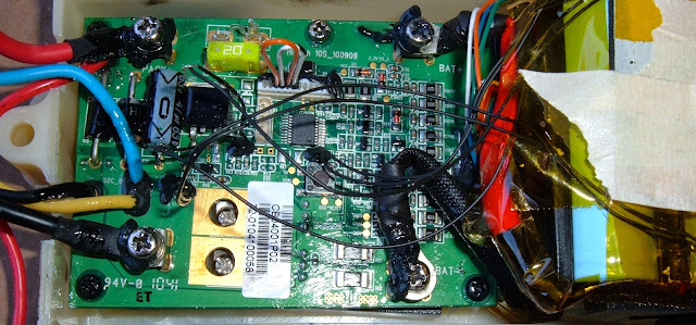
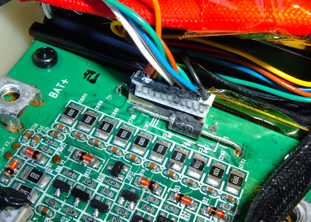
This is the BMS. It's a "Hitech 10S_100909" - I can't find a thing about that BMS, so I'm treating it as a black box, sadly. There's not much in terms of labeling either. If anyone happens to know anything about this BMS, I'd love more information.
The BMS has a pretty good amount of black goop over the various screws and connectors, so nothing is likely to come loose - well done! I'm a little bit concerned about the missing cover over the top fuse, but the fuse seems intact, so... it's probably fine. I'm not going to worry about it that much as long as things work. I later found out the damage to the fuse was a result of the previous owner trying to remove it forcably before realizing it was soldered down. It's not the worst electrical surprise I've ever found in a used vehicle, and the fuse seems to be fine.
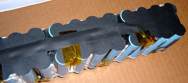
The top tape comes off easily, showing us the batteries.
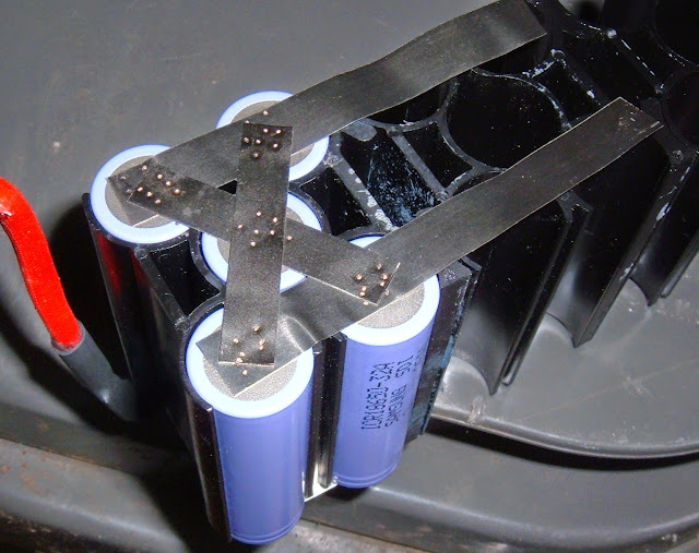
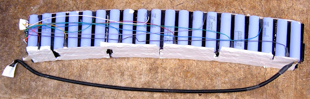
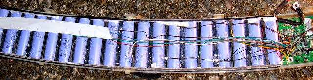
The battery pack looks somewhat complicated, but it's really not. The black wires along the top are just temperature sensors, and the yellow tape is holding the per-cell sense wires in place.
Battery packs consist of groups of physical cells wired in parallel to form larger cells, and then these larger cells are wired in series to form the full battery. Each cell (of one or more physical cells) has wires going to the BMS so the voltage can be sensed and the pack can be balanced. And, in a good system (such as this one), there are thermal cutoffs that will cut power to/from the pack if it gets too hot.
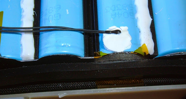
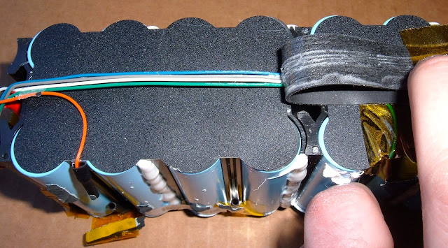
The thermal sensors are just glued down to the pack and then covered with tape - this seems entirely reasonable as a way to communicate to the BMS that the pack is overheating, though I'd like to see them extend a bit further down the pack. The far end of the pack has no thermal sensors at all.
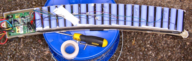
After removing the thermal sensors (they just pop right off), the next step is to free up the sense wires going from the BMS to each cell. They're in a wide plug, right at the end of the BMS. It was well gooped into place, but once I cleared that out, it popped out cleanly. I'll need this harness when I rebuild the pack.
After getting that connector free and unscrewing the battery pack terminals, the whole pack comes out (slowly). It's secured to the other side of the pack with double sticky tape, but a bit of prying and some patience solves this.
Battery Cells Teardown
Alright! The actual battery pack is out of it's casing. It's time to tear this one down so I can replace the cells. Copious notes have been taken so I can have a chance of putting it back together right...
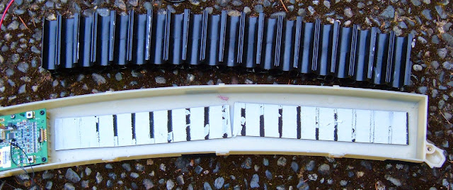
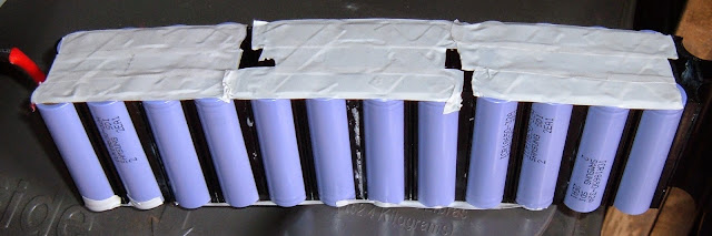
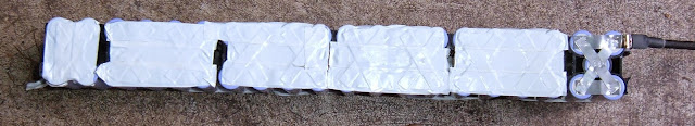
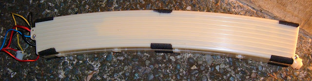
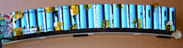
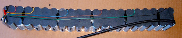
The pack is held together by black plastic retainers. The positive and negative terminals go, as expected, to the opposite ends of the pack (so there's nothing goofy like an out-and-back pattern). It's a pretty standard looking pack, other than the slight curve to it.
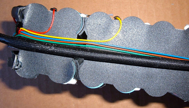
If we take a quick look, there's padding tape down the sides, and the sense wires are protected by more tape. Nothing unusual so far.
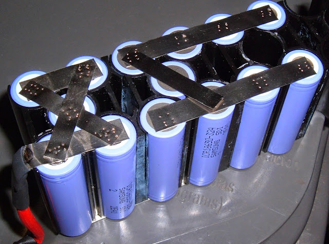
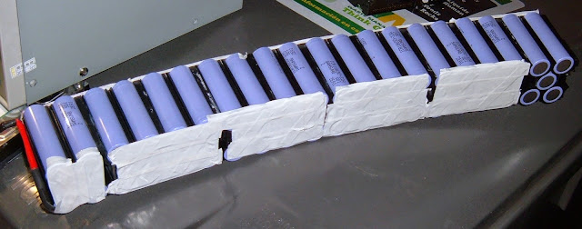
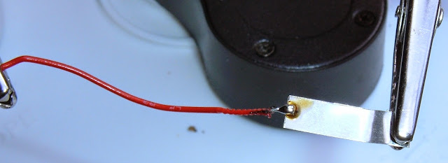
This picture shows the sense wires going down the sides of the pack. There's one wire to each voltage region (so for the 10 cells, 11 total wires - yay fencepost errors). They are soldered to the metal plate joining the packs, and are easy enough to remove by snipping the metal sheet.
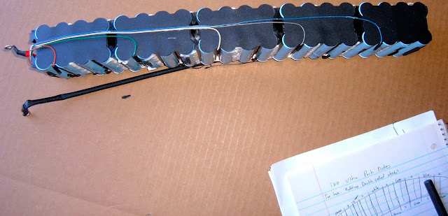
When rebuilding, it's VERY important that the wires go to the same places. Notes matter here - you can see some of mine in the picture.
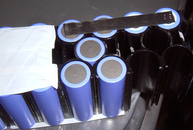
With the BMS monitoring wires documented, it's time to pull off the plastic insulation and see what's under there.
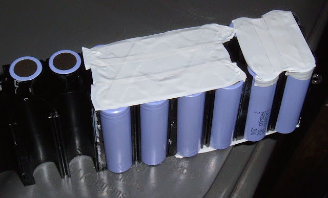
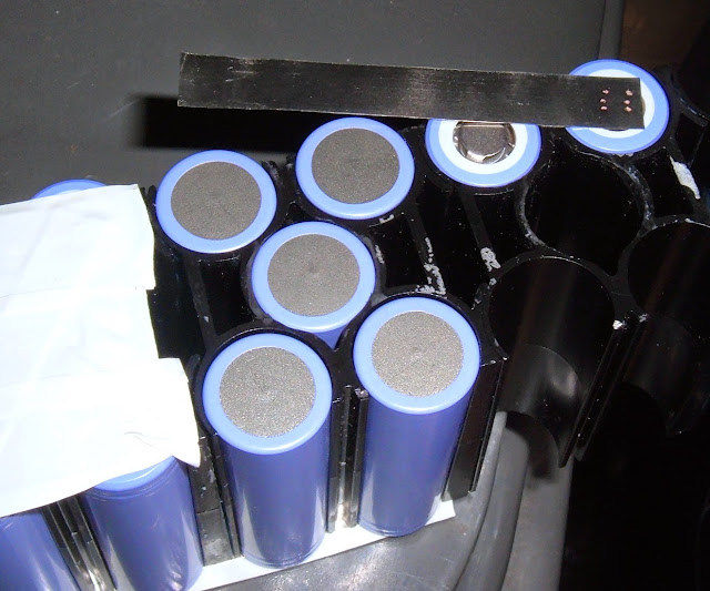
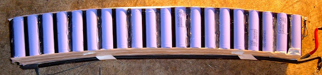
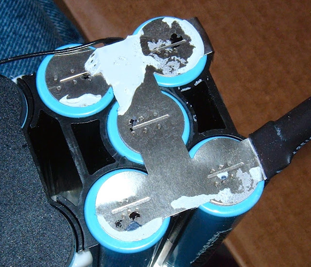
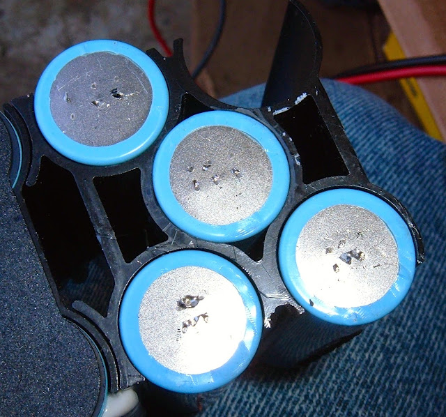
And... woah. 5 cells! Up until this point, I thought there were only 4 18650s per cell - this explains a lot about the pack size and amperage.
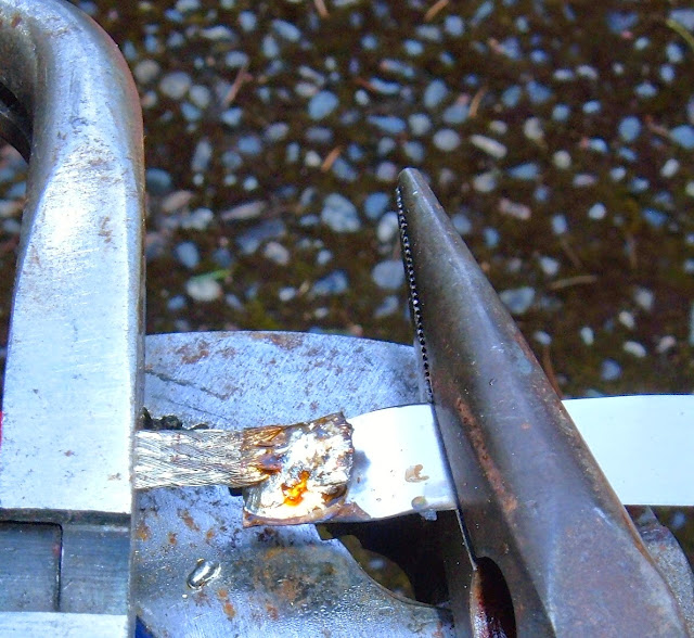
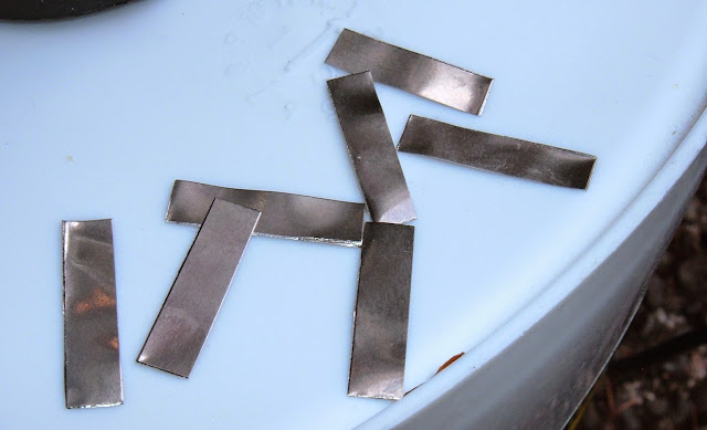
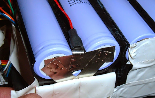
You can see from these pictures that the metal strips used to secure the pack are custom cut for this pack. The slot in the middle for each cell is for spot welding - it helps force the current through the end of the cell and makes a better weld. Nicely done! No complaints here.
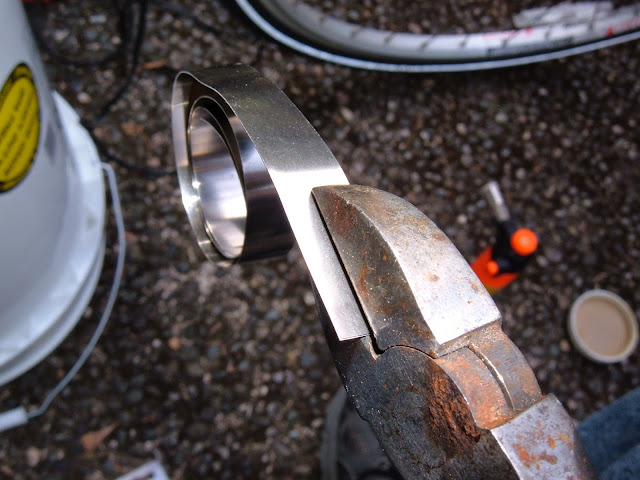
Measurement of the metal with a micrometer indicates it's 0.2mm thick, and I assume it's nickel, because that's what's used to spot weld battery packs together.
Well, now that everything is cleared out of the way, I can find out what's in here.
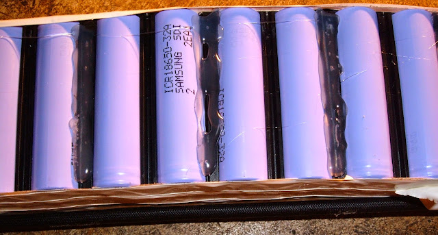
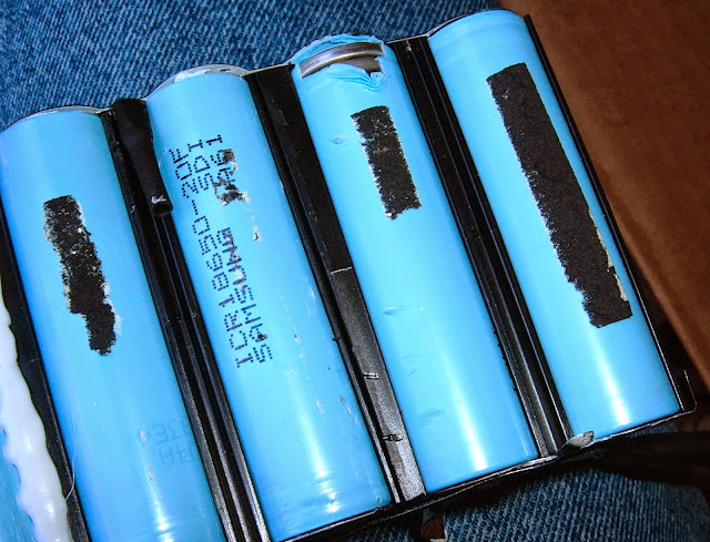
The pack is a 10S5P pack composed of Samsung ICR18650-20F cells. That's a 2000mah cell, so with 5 per cell, the 10AH rating for the pack is legit. Don't mind the removed insulation - I was checking to see if it had protection circuitry on a per-cell level. It doesn't (which is fine, with a pack BMS).
If we flip the pack over and remove insulation on the other side, it's the same type of metal stripping, custom cut for the pack. Nothing fancy to see here. This is a positive terminal and negative terminal joined together (and if you look towards the bottom, you can see the tab where the sense wire was connected - I just snipped them off).
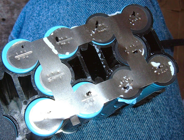
Pulling the interconnect strips off, it was very well attached - you can see the fragments left where the stripping was attached to the cells. That's a sign of good welds.
A little bit of time later, a bunch of welds popped, some connections snipped, and this is what's left of the pack!
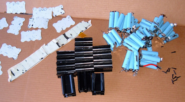
Pack Summary
Alright. The pack is apart. So, what's in it?
The core of the bike's power is 50x Samsung ICR18650 cells, 2AH/ea. They're in a 10S5P arrangement for a 36v nominal voltage and 10AH worth of capacity. In a moment of minor surprise, the actual arrangement of the cells matches what the pack is rated at! Impressive!
The battery management system, despite having labels, isn't something I can find any information on. So, sadly, I have to treat it like a black box. If you happen to have any manuals for it, I would absolutely love them.
There are some black spacers, and that's about it. Pretty simple!
The canonical posts are here:
Part 1: http://syonyk.blogspot.com/2015/05/izip-ultra-2011-battery-pack-teardown-1.html
Part 2: http://syonyk.blogspot.com/2015/05/izip-ultra-2011-battery-pack-rebuild-2.html
Part 3: http://syonyk.blogspot.com/2015/05/izip-ultra-pack-rebuild-33.html
But, for ES, I'll copy/paste them here.
Warning. Long.
===================================================
iZip Ultra 2011 Battery Pack Teardown 1/3
2011 iZip Ultra Battery Pack Rebuild
Someone at work was getting rid of an ebike they were sick of. It didn't work. One of my flaws is that I'm a sucker for free stuff I'm interested in, especially if it originally sold for a lot of money. Please ignore the stack of phones and tablets on my desk that I need to fix or strip for parts...
A quick trip to pick it up, and I had the following sitting in my garage:
It's a 2011 Currie iZip Ultra. This is a 500W geared rear hub motor, pedal assist ebike, with a 36v, 10AH pack. Of note are the very small, high pressure tires - it's supposedly quite efficient as far as power use goes, even on a higher assist setting.
Unfortunately, this one wasn't going to do any assisting at all. The battery pack was stone dead. I got a back story involving the charger, a power outage, and the pack dying, so perhaps the charger drained it after the power outage, but whatever the case, it was dead. Really, really dead.
The bike uses lithium cells - ICR (LiCoO2) cells to be specific. Lithium cells are great in terms of power density and energy density, but they require some specialized care and feeding. They must exist in a voltage range between about 2.7 and 4.3 volts per cell (and spend most of their life in the upper 3v region).
Discharging a lithium cell below 2.7 volts tends to do physical damage to the cell if it's left there (and, really, you shouldn't ever have them below 3v/cell for any length of time). Skipping to the punch line, this is a 10S pack. That means the pack should live between 30v and 43v. Maybe down to 27v, briefly.
10 volts for the whole pack is right out. That's "bad." That voltage, combined with the time sitting, means the pack is physically damaged, recharging the batteries is not a good idea, and even if it will take a charge, it's very likely significantly short on capacity. Individual cells were between about 0.6v and 1.2v. Neither is 2.7v or greater...
A replacement OEM pack is $600. A bit of research indicates that I can do a lot better. So, of course, I tried to.
This teardown was done against the best advice of warning stickers, totally voiding any remaining warranty on the pack (not that there was one 4 years later), and is definitely not a good idea. So, of course, I continued. iZip had nothing to do with this teardown and isn't responsible for any of the stuff I did to their pack.
Full Pack Overview
The pack lives in the thick frame tube, arching up from the pedals to the steering bearings. It's surprisingly easy to remove, though - remove a few screws, the bottom of the tube (containing the controller) drops out, and the pack follows quickly. It looks sort of like a banana.
There are two three-pin connectors coming off the pack to disconnect before removing it. One (the triangular connector with thicker wires) goes to the motor controller. The other (thinner wires) connects via a cable to the external charging port up higher on the tube.
The black and red wires on the "triangle" plug are power and ground. I'm not entirely sure yet what the blue wire is, but I believe based on some conversations with iZip that it's a voltage sense wire (it just happens to be a lot larger than needed).
A close inspection of the end of the pack indicates that I'm going to void the warranty if I remove the sticker. Fortunately, the sticker is still there - just sliced! I should note here that the previous owner did pop the pack open when it died, so I'm not the first to be in here.
"For safety and function reasons, user's disassembly is not allowed. Please contact a qualified dealer for service. Warranty void if this sticker removed."
Well... the warranty is void anyway. According to the information that came with the bike, the warranty for the battery is "Lithium-ion type: One year (12 months) from purchase date by original owner. Warranty is void in the event proper care instructions as per the owner’s manual are not followed." One year warranty? This is why I like LiFePO4... Also, I'm reasonably confident fully draining the pack is not proper care. It doesn't matter anyway as it's a 4 year old bike.
Two bolts and a bunch of snaps hold the shell together. Remove them, and in we go!
Pack Insides
The first view we get with the shell off is the BMS (Battery Management System), some padding tape and a whole lot of batteries. As this is a battery pack, that's a good thing. The cells are 18650s, which is great - they're a standard size and easy to obtain.
This is the BMS. It's a "Hitech 10S_100909" - I can't find a thing about that BMS, so I'm treating it as a black box, sadly. There's not much in terms of labeling either. If anyone happens to know anything about this BMS, I'd love more information.
The BMS has a pretty good amount of black goop over the various screws and connectors, so nothing is likely to come loose - well done! I'm a little bit concerned about the missing cover over the top fuse, but the fuse seems intact, so... it's probably fine. I'm not going to worry about it that much as long as things work. I later found out the damage to the fuse was a result of the previous owner trying to remove it forcably before realizing it was soldered down. It's not the worst electrical surprise I've ever found in a used vehicle, and the fuse seems to be fine.
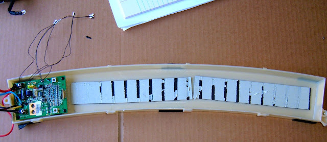
The top tape comes off easily, showing us the batteries.
The battery pack looks somewhat complicated, but it's really not. The black wires along the top are just temperature sensors, and the yellow tape is holding the per-cell sense wires in place.
Battery packs consist of groups of physical cells wired in parallel to form larger cells, and then these larger cells are wired in series to form the full battery. Each cell (of one or more physical cells) has wires going to the BMS so the voltage can be sensed and the pack can be balanced. And, in a good system (such as this one), there are thermal cutoffs that will cut power to/from the pack if it gets too hot.
The thermal sensors are just glued down to the pack and then covered with tape - this seems entirely reasonable as a way to communicate to the BMS that the pack is overheating, though I'd like to see them extend a bit further down the pack. The far end of the pack has no thermal sensors at all.
After removing the thermal sensors (they just pop right off), the next step is to free up the sense wires going from the BMS to each cell. They're in a wide plug, right at the end of the BMS. It was well gooped into place, but once I cleared that out, it popped out cleanly. I'll need this harness when I rebuild the pack.
After getting that connector free and unscrewing the battery pack terminals, the whole pack comes out (slowly). It's secured to the other side of the pack with double sticky tape, but a bit of prying and some patience solves this.
Battery Cells Teardown
Alright! The actual battery pack is out of it's casing. It's time to tear this one down so I can replace the cells. Copious notes have been taken so I can have a chance of putting it back together right...
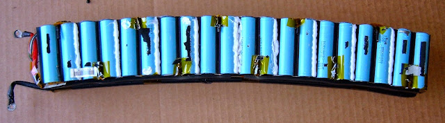
The pack is held together by black plastic retainers. The positive and negative terminals go, as expected, to the opposite ends of the pack (so there's nothing goofy like an out-and-back pattern). It's a pretty standard looking pack, other than the slight curve to it.
If we take a quick look, there's padding tape down the sides, and the sense wires are protected by more tape. Nothing unusual so far.
This picture shows the sense wires going down the sides of the pack. There's one wire to each voltage region (so for the 10 cells, 11 total wires - yay fencepost errors). They are soldered to the metal plate joining the packs, and are easy enough to remove by snipping the metal sheet.
When rebuilding, it's VERY important that the wires go to the same places. Notes matter here - you can see some of mine in the picture.
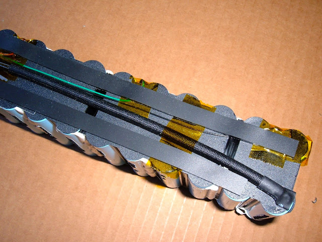
With the BMS monitoring wires documented, it's time to pull off the plastic insulation and see what's under there.
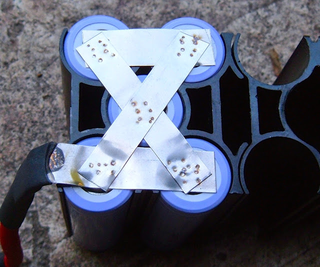
And... woah. 5 cells! Up until this point, I thought there were only 4 18650s per cell - this explains a lot about the pack size and amperage.
You can see from these pictures that the metal strips used to secure the pack are custom cut for this pack. The slot in the middle for each cell is for spot welding - it helps force the current through the end of the cell and makes a better weld. Nicely done! No complaints here.
Measurement of the metal with a micrometer indicates it's 0.2mm thick, and I assume it's nickel, because that's what's used to spot weld battery packs together.
Well, now that everything is cleared out of the way, I can find out what's in here.
The pack is a 10S5P pack composed of Samsung ICR18650-20F cells. That's a 2000mah cell, so with 5 per cell, the 10AH rating for the pack is legit. Don't mind the removed insulation - I was checking to see if it had protection circuitry on a per-cell level. It doesn't (which is fine, with a pack BMS).
If we flip the pack over and remove insulation on the other side, it's the same type of metal stripping, custom cut for the pack. Nothing fancy to see here. This is a positive terminal and negative terminal joined together (and if you look towards the bottom, you can see the tab where the sense wire was connected - I just snipped them off).
Pulling the interconnect strips off, it was very well attached - you can see the fragments left where the stripping was attached to the cells. That's a sign of good welds.
A little bit of time later, a bunch of welds popped, some connections snipped, and this is what's left of the pack!
Pack Summary
Alright. The pack is apart. So, what's in it?
The core of the bike's power is 50x Samsung ICR18650 cells, 2AH/ea. They're in a 10S5P arrangement for a 36v nominal voltage and 10AH worth of capacity. In a moment of minor surprise, the actual arrangement of the cells matches what the pack is rated at! Impressive!
The battery management system, despite having labels, isn't something I can find any information on. So, sadly, I have to treat it like a black box. If you happen to have any manuals for it, I would absolutely love them.
There are some black spacers, and that's about it. Pretty simple!