Rectifier Huawei R4850G2 48V 42~58V 3000w

I found the answer. The R4875 unit has a third pair of control contacts on the connector. These contacts need to be closed between themselves. After closing the contacts, the unit outputs more than 60 amperes. There are connectors specifically for the R4875 unit. They have a third pair of control contacts, and a jumper is already installed in the connector. One manufacturer has the contacts connected, and the other has the connector in an insulating cap.
1.JPG
2.JPG
3.jpg
R4875G1.png
 
Great find. :bigthumb: I will try it not tomorrow. :(
I first have to get the right plug, my plugs do not have the option to ad that pin.

Have you found the manual for the R4875

Do you know how the R24/4850 is switched between 24V and 48V or is this done via CAN?
I'm still looking for a 24V rectifier.
 
dominik h said:
Great find. :bigthumb: I will try it tomorrow.
Have you found the manual for the R4875

Do you know how the R24/4850 is switched between 24V and 48V or is this done via CAN?
I'm still looking for a 24V rectifier.
I don't have a technical description for the R4875.
R24/4850N1 is some kind of old and rare device. I've never come across such. I can't say anything at least.
There are Flatpack2 26.7V/75A units at 24 Volts
 
I know about the flatpack 24V but they are to expensive for me (used >over 400€) . Can get the huawei for half the price.
 
Does anyone know where you can buy a Bluetooth card to control the R4875 unit? I can't find a seller in China. Maybe someone has contacts.
 
TIOK said:
I found the answer. The R4875 unit has a third pair of contacts on the connector. These contacts need to be closed between themselves. After closing the contacts, the unit outputs more than 60 amperes. There are connectors specifically for the R4875 unit. They have a third pair of contacts, and some already have a jumper, and some need to be installed.
1.JPG
2.JPG
3.jpg
R4875G1.png

great find, i will mod mine too :bigthumb:
 
Does anyone know why the huawei r4850 do not give any voltage when they are connected in series? If I open the serial DC-output connection they imidiatly give me 53.5V.

I use the Eltek FP2 in series without any problems.
20220920_072746.jpg
 
Looking at my picture 4 hours later gives me the solution, I did not make a series connection , I shorted them. :cry:

Now they are working.
20220920_121547.jpg
 
4kw R4875 works now with the right plug.
Giving 3 seconds up to 4,4kw.
 

Attachments

  • 20220920_140639.jpg
    20220920_140639.jpg
    3.9 MB · Views: 1,475
  • 20220920_140549.jpg
    20220920_140549.jpg
    3.4 MB · Views: 1,474
Hey everyone,

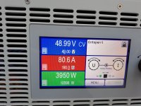
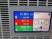
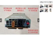
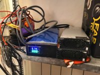
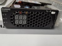
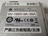
I have been testing 4 R4850G2s in parallel to charge a 16s LiFePO4 pack with some great results in terms of amperage and voltage control. After receiving the units I used a USB-CAN analyzer to change the Off-line default voltage to 50V and the Off-line default current to 30A. During a charge cycle I set the On-line voltage to 55V and On-line current to 30A - Repeat packets every 45 seconds until the charge is complete.

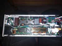
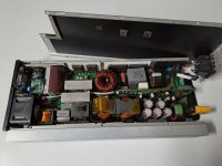
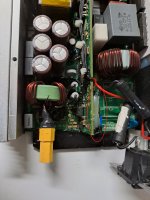
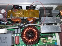
The problem is the fans on the R4850G2s don't change speed and the units are generating a huge amount of heat during charging. They hit between 60-73c after only 20mins.
temp.jpg

I noticed a few people have had problems with fans running full speed with no load, the only condition I could find this happened in one unit dated 2015 spins up full when no CAN communication is detected, as soon as you connect it to the CAN bus it drops back down. Also noticed fans ramp up slightly when the battery is disconnected from the DC output. Once you reconnect the battery it ramps back down.

Clearly the fans do work to some degree but oddly not during extreme heat conditions when you need them to be 100%. Also would have expected the one R4850G2 that reached over 70c to shutdown or throttle but it continues to run regardless.

Could be some flag that needs setting to automatically control the fans, perhaps they are set in manual mode and are expecting a SMU02 module to change the speed depending on temp. Observing Unknown frame 83 during a charge cycle shows 01 83 00 00 10 00 00 00 for a few minutes before returning back to 01 83 00 00 00 00 00 00. I believe this could be a flag to indicate a fan error.

Does anyone have any idea why they refuse to ramp up? anymore have experience with a SMU02 controller, does it have any settings for fan control?

Any help would be much appreciated.

Thanks for looking and stay safe.
 
https://endless-sphere.com/forums/viewtopic.php?f=14&t=86038&p=1733123#p1733142

dominik h

In series you got 218v output, right ?
so how your 4.4kw output is 48.99 v-51.98v on multi ??
what is 80a ~?

bg
 
The setup with 4x3kw in series with 218V is to charge a hv-battery. Only with 25A.

The second picture is a single 4kW Huawei on the electronic load to test if I get the nominal 80A and 4kw from it after 4 hours fully loaded.
The third picture is to show the short time power from the 4kw.
At higher voltages the psu overshoots the nominal 4kw power up to 10% for a few seconds when changing the load slightly.
 
I have SMU02B. There are no fan settings in it.
You can only see the temperature of each unit.
 
OhmSchool said:
VK3AMP said:
What changes need to be made to the code to control 2 r4850 modules in parallel?

Wow, 2x r4850s in parallel? That would produce 56 x 2 = 112 amps DC and 42 amps of 240v AC current at full load. Curious to know what on earth could be drawing 6000 watts DC?? Hoping the cost of electricity :bolt: is low in your area.


İt will be used to power a 4kw hf amplifier.

And the electricity is certainly not cheap in Australia. :)
 
VK3AMP said:
OhmSchool said:
VK3AMP said:
What changes need to be made to the code to control 2 r4850 modules in parallel?

Wow, 2x r4850s in parallel? That would produce 56 x 2 = 112 amps DC and 42 amps of 240v AC current at full load. Curious to know what on earth could be drawing 6000 watts DC?? Hoping the cost of electricity :bolt: is low in your area.


İt will be used to power a 4kw hf amplifier.

And the electricity is certainly not cheap in Australia. :)

A man after my own interests love the idea of it get a thread up on it, i done a 2000w system in my house nearly 10 years ago now using hp psu i remeber a fellow old boy spark saying to get 12v over 160 amps in the house would take a huge transformer then within the year of digging id sourced 2 psu for £15 a pair smaller than a suitcase.

The system i made used a 12 inch pioneer premiere sub the thing was evil it cracked my door frame of the wall flexing my whole room.
 
thanks dominik h

anyone know well modification to get 100.8v from single psu ?
all information about blue potentionemtezrvand wiring are welcome
 

Attachments

  • IMG20190418205218397.jpg
    IMG20190418205218397.jpg
    1.3 MB · Views: 1,316
  • çuhguihgpuih.jpg
    çuhguihgpuih.jpg
    144.4 KB · Views: 1,310
These chinese modified Huawei do not last very long.
Mine died after a few hours of charging. Had the 100V 30A version. Rewind transformer , an extra pcb, a lot of small wires and a lot of glue is all I can see in mine.
 
First of all

it feels they remove one inductance post and one capacitor post on primary
dominik h say they rewiring transformers , does it is transformers on secondary ?
i'm not sure about that, they used some blue "potars" to manage voltage looks like at input and output

rewiring bobinage transformers could be difficult if you don't know number of coils
and i don't think they manage ouput voltage and current by the can bus control

after that they just picks some low voltage for voltmetter at good place

be sure i'm interesting of seeing psu without white glue to understand the process

regards,
 

Attachments

  • IMG_20221002_205532.jpg
    IMG_20221002_205532.jpg
    1.1 MB · Views: 1,252
TIOK said:
I have SMU02B. There are no fan settings in it.
You can only see the temperature of each unit.

Thanks for looking and getting back to me.
I may have to hardwire them to a 5 or 9v rail until I have time to pull the flash off the MCU and see what I can find... If anything :lol:
 
My defective 100V Huawei
 

Attachments

  • 20221010_161536.jpg
    20221010_161536.jpg
    3.5 MB · Views: 1,038
  • 20221010_161510.jpg
    20221010_161510.jpg
    4.2 MB · Views: 1,036
  • 20221010_161452.jpg
    20221010_161452.jpg
    3.6 MB · Views: 1,033
  • 20221010_161412.jpg
    20221010_161412.jpg
    2.6 MB · Views: 1,036
  • 20221010_161331.jpg
    20221010_161331.jpg
    2.8 MB · Views: 1,036
  • 20221010_161323.jpg
    20221010_161323.jpg
    2.7 MB · Views: 1,036
  • 20221010_161318.jpg
    20221010_161318.jpg
    2.6 MB · Views: 1,034
  • 20221010_161314.jpg
    20221010_161314.jpg
    2.8 MB · Views: 1,043
dominik h said:
My defective 100V Huawei


hi dominik h
thanks for the add !

I see little much better
1. about your psu, red and black input wire looks to thin for 3kw, and asking me about simple black fuse maybe burnt
2. there is a real special pcb board added with "blue pots" glued at the back, it is probably the way to add 0-30v to the wattmeter in front panel
3. Something happened on the 2 lateral mosfets, and asking me about the 100v dc, habitually fets works in parallels, and here it is wired weird by drain, (need more photos on 3pins of each)
4. i need more photos of front panels disassemble because your "pots" speaks from the mosfets with your front wattmeter to check power
5.there is a special pcb to control the fan and i willn't be surprised that why there is a "special shunt resistor" for in the back of the card (1st photo)

regards,
 

Attachments

  • 1.jpg
    1.jpg
    821.2 KB · Views: 1,004
  • 2.jpg
    2.jpg
    1.3 MB · Views: 1,006
More Pins
 

Attachments

  • 20221012_205330.jpg
    20221012_205330.jpg
    2.4 MB · Views: 957
  • 20221012_205336.jpg
    20221012_205336.jpg
    2.1 MB · Views: 957
hi

here is some pcb for the modification
if you can react about the wiring ...
 

Attachments

  • Sd80368542ced4179b4518f81082156d4r.jpg
    Sd80368542ced4179b4518f81082156d4r.jpg
    184.7 KB · Views: 962
Back
Top