I get some details
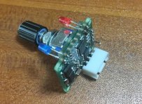
Power Module Control Board Description
Here, the communication power module is defined as a 48V battery charger (for lead-acid/lithium-powered 48V batteries).
This universal control board is suitable for Emerson R48 series power modules. It is controlled by communication protocol. It is easy to operate. The power module does not make any changes. Just connect the power supply and communication interface. The R48-500/1000/1800/2900/3200 has been tested and is theoretically supported by the R48 full range. As for other models to be tested and verified. The voltage is regulated from 41.5V to 58.5V, and the current regulation is 10% to 120% set according to the rated current percentage.
The control board does not have a display, and the voltage and current display needs to be processed by itself or directly added to the output circuit.
***Special instructions on the working of the power module offline and communication online, many people do not understand this.
1. The power module works offline, that is, the communication port of the module has no communication connection, but it is powered on separately. Generally, the panel orange light will flash after 40 seconds of power-on, which means there is no communication prompt. At this point, the output voltage of the power supply is the default output voltage of the module (many are 53.5V), and this default output voltage can be changed from 48V to 58.5V.
2. The power module works online, that is, the communication port of the module has communication connection and the communication is normal, and the orange light does not flash on the panel. At this time, the power supply output voltage is controlled by the communication port communication, and the range is slightly wider from 41.5V to 58.5V. This control board controls the power module output in real time.
***About the control panel function description,
The control board has two key functions, changing the default output voltage of the power supply and connecting the power supply to adjust the output voltage in real time.
1. Change the default output voltage of the power supply. When the control board is normally connected to the power module for 10 seconds, the control board will send the default output voltage data to the power module. This data is a fixed value. The range is 48V~58.5V, 0.1. V stepping. After 10 seconds to change the default output of the power module, you can disconnect and remove the control board. The power module works offline again. The output voltage is the default voltage after the change. The voltage setting sent by the control board needs to be connected to the computer through the serial cable to preset to be saved in the control panel.
2. Adjust the output of the power module in real time. The control board is connected to the power module normally. It is always connected. After power-on, the output of the power module can be controlled in real time through the knob of the control board. The output voltage is 41.5V~58.5V, stepping 0.1V. The current limit is 10% to 120% of the rated value and the step is 1%.
3. To change the default output voltage of the power supply, only the control board is normally connected for about 10 seconds, and the real-time control power supply module needs to be connected to the power module normally. Real-time control permissions are higher than the default output permissions.
Function: (Red light / blue light is always on in normal working mode)
1. Voltage regulation 41.5V ~ 58.5V (0.1V step)
Double-click the button to enter the voltage adjustment mode, the red light flashes, the blue light is always on, and the knob is rotated to adjust the voltage. Do not do anything for more than 8 seconds, and exit the function mode to the normal working mode. Each time the power module is powered back on, it will run the last adjusted value.
2. Current limiting adjustment, 10%~120% according to the rated current percentage (1% step)
The first time you double-click the button to enter the voltage adjustment mode, double-click the button again to enter the current limit adjustment mode, the red light is always on, the blue light is flashing, and the rotary knob adjusts the current limit. Double-click the button again to exit the function mode to the normal working mode, or do nothing for more than 8 seconds, and exit the function mode to the normal working mode. Each time the power module is powered back on, it will run the last adjusted value.
3. The module resets and restarts.
If the power module is shut down in case of failure, in any mode, press and hold the button for more than 6 seconds, the red/blue light flashes at the same time, and the power module resets and restarts.
4. Under voltage to turn off the power, (this function can be selected to turn off or on)
If the power supply encounters a fault or has a heavy load and the output voltage drops to less than 36V, the power output is turned off for 5 seconds. After the problem is removed, the power module is powered off and restarted, or the button is held down for more than 6 seconds.
5. The battery is fully delayed to turn off the power module output (you can choose to turn off this function, no delay shutdown)
When the battery is fully charged, the current starts when the current drops to 0.3A, and the power module output is turned off after the time is reached. (Delay time is 1 minute to 240 minutes optional) After the power module is powered off, it can be restarted, or the button can be reset for more than 6 seconds.
6. Change the default output voltage of the power module (when there is communication access, the output voltage is the voltage adjusted by the control panel in real time)
This voltage is the output voltage when the power module is not connected for communication and works offline. The range is 48V to 58.5V, with 0.1 steps.
For example, if the power module wants to change the default voltage to 50V, the control board needs to connect the serial port to the default output voltage of 50V. Then the control board can be connected to the power module for normal operation. Then the output voltage of the power module is 50V. It is. (The common default output voltage on the market is 53.5V)
Huawei
Foreword: The communication power module is defined here as a 48V charger (for lead-acid/lithium-powered 48V batteries).
This universal control board is suitable for Huawei 48 series high-efficiency power supply module. It is controlled by communication protocol. It is easy to operate and the power module does not change. Just connect the power supply and communication interface. 4815N; 4830N; 4850N/G have been tested and available, and other models are to be tested and verified. Voltage regulation 41V ~ 58.5V, current adjustment 0 ~ 60A (rated maximum) The control board does not have a display, the voltage and current display must be added in the power module itself, or directly added to the output loop.
***Special instructions on the working of the power module offline and communication online, many people do not understand this.
1. The power module works offline, that is, the communication port of the module has no communication connection, but it is powered on separately. Generally, the panel orange light will flash after 40 seconds of power-on, which means there is no communication prompt. At this point, the output voltage of the power supply is the default output voltage of the module (many are 53.5V), and this default output voltage can be changed from 48V to 58.5V.
Special note: Huawei can also change the default output current limit, ranging from 0 to 60A (maximum rating). This is great. After setting the default output of the power module we requested, let it work offline.
2. The power module works online, that is, the communication port of the module has communication connection and the communication is normal, and the orange light does not flash on the panel. At this time, the power supply output voltage is controlled by the communication port communication, and the range is slightly wider from 41.5V to 58.5V. This control board controls the power module output in real time.
***About the control panel function description,
The control board has two key functions, changing the power default output and connecting the power supply to adjust the output in real time.
1. Change the default output of the power supply. If the control board is normally connected to the power module for 10 seconds, the control board will send the default output voltage and current limit data to the power module. This data is a fixed value. The voltage range is 48V~58.5. V, 0.1V stepping, the current limiting range is selected from 0 to 60A. After changing the default output of the power module for 10 seconds, you can disconnect and remove the control board. The power module works offline again. The output voltage is the default value after the change. The default setting sent by the control panel needs to be connected to the computer through the serial cable to preset to be saved in the control panel.
2. Adjust the output of the power module in real time. The control board is normally connected to the power module. After power-on, the output of the power module can be controlled in real time through the knob of the control board. The output voltage is 41.5V~58.5V, stepping 0.1V, and the current limit is Rated 10% to 120%, step by 1%.
3. To change the default output of the power supply, only the control board is normally connected for about 10 seconds, and the real-time control power supply module needs to be connected to the power module normally. Real-time control permissions are higher than the default output permissions.
Function: (Red light / blue light is always on in normal working mode)
1. Voltage regulation 41.5V ~ 58.5V (0.1V step)
Double-click the button to enter the voltage adjustment mode, the red light flashes, the blue light is always on, and the knob is rotated to adjust the voltage. Do not do anything for more than 8 seconds, and exit the function mode to the normal working mode. Each time the power module is powered back on, it will run the last adjusted value.
2. Current limiting adjustment 0A ~ 60A (0.1 step)
The first time you double-click the button to enter the voltage adjustment mode, double-click the button again to enter the current limit adjustment mode, the red light is always on, the blue light is flashing, and the rotary knob adjusts the current limit. Double-click the button again to exit the function mode to the normal working mode, or do nothing for more than 8 seconds, and exit the function mode to the normal working mode. Each time the power module is powered back on, it will run the last adjusted value.
3. Maximum output current limit value
The control panel can be set to adjust the maximum value of the current limit value, ranging from 0 to 60 A. This value directly affects the current limit when the maximum output current limit and the default output are adjusted in real time. For example, if we set this current limit value to a maximum of 15A, then the knob adjustment can only be up to 15A in real-time control. The same is true for setting the default output current limit of the power module.
4. Change the default output of the power module (when there is communication access, the output is adjusted in real time by the control panel)
This output is the default output voltage when the power module is not connected for communication and works offline. The range is 48V to 58.5V, with 0.1 step, default output current limit, selectable range 0~60A (maximum rating), 0.1 Stepping.
For example, if the power module wants to change the default voltage to 50V, the control board needs to connect the serial port to the default output voltage of 50V. Then the control board can be connected to the power module for normal operation. Then the output voltage of the power module is 50V. It is. (The common default output voltage on the market is 53.5V)