MadRhino
100 GW
Yep. Try to use copper wire size to match shunt size.
^^This^^ I didn't think of that, but that makes perfect sense, and is probably the failure. Whatever failure mode the LM358 has may create an output that is whatever the controller thinks is too high a current, so it's refusing to operate.fechter said:Most controllers I've seen use something like a LM358 to measure the voltage across the shunt. Normally the input would be millivolts, but if the shunt resistors were all open circuit, the LM358 (or whatever is looking at the shunt voltage) could see full pack voltage and self-destruct.
amberwolf said:Solder has higher resistance than wire, especially copper, so it would actually work *better* across a broken shunt than copper, for doing the job the shunt would do.
But even a zero resistance shunt (pure copper) would still allow the controller to "work", but it would have no way of knowing it was putting far too much current thru the FETs, and could easily destroy itself under loaded conditions.
^^This^^ I didn't think of that, but that makes perfect sense, and is probably the failure. Whatever failure mode the LM358 has may create an output that is whatever the controller thinks is too high a current, so it's refusing to operate.fechter said:Most controllers I've seen use something like a LM358 to measure the voltage across the shunt. Normally the input would be millivolts, but if the shunt resistors were all open circuit, the LM358 (or whatever is looking at the shunt voltage) could see full pack voltage and self-destruct.
It's also possible that the circuit design allowed the high voltage to be available on the MCU input pin itself, and then the MCU would be damaged and the controller essentially toast.
amberwolf said:All that part does is translate the shunt voltage into what the MCU needs so it can understand how much current is flowing.
It isn't part of the LVPSU (12v & 5v) regulation system.
BTW, the controller doesn't output 72v--that's just your battery.
fechter said:Can you post a good picture of the controller board? You may be able to trace out the circuit and find a spot to test the current amplifier.
ebike11 said:https://ibb.co/JtW9mPb
https://ibb.co/8jdSfv1
https://ibb.co/QQH87yv
https://ibb.co/0Y0rnWG
https://ibb.co/wdbtH6j
DogDipstick said:ebike11 said:https://ibb.co/JtW9mPb
https://ibb.co/8jdSfv1
https://ibb.co/QQH87yv
https://ibb.co/0Y0rnWG
https://ibb.co/wdbtH6j
What is the numbers on the top right of this board? Is that a 618 - or a 318 -?
I can't see all the pics, but there's one that does show the three shunts.ebike11 said:You can see the shunt i damaged in the center of the board. I can take more if needed.
amberwolf said:I can't see all the pics, but there's one that does show the three shunts.ebike11 said:You can see the shunt i damaged in the center of the board. I can take more if needed.
None of them are connected to their other end.
Until there is a connection across the two ends of the shunt, nothing can work, becuase the FETs (and possibly other stuff) has no battery negative connection.

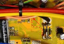
fechter said:What looks to be the current sensing line is marked in the pic below. I can't see where it goes under the wires. Look to see where that trace goes. In this model of controller, possibly the current sensing amplifier is integrated into the main MCU chip. There may be a resistor in series between the sensing line and the MCU that should be checked. If there are no obviously failed parts outside the MCU, it will probably be hopeless as replacing the MCU is not likely to be possible.
Controller sense line.jpg
docw009 said:How about you just make a new shunt with copper wire. See if the motor turns. If not, you cannot fix it. Throw the controller out or save it to steal spare parts like capacitors.
Very few of us have the skills, tools, and eyesight to replace a surface mount component. Twenty years ago, I could do the simpler ones with a heat gun and solder pencil, but not now,
ebike11 said:Hi again..oh i checked as you posted.
It does lead to some chip of some sorts..dont know the terminology. Its the one next to the purple dot.
Is this of any help?
https://ibb.co/phvQTyJ
fechter said:ebike11 said:Hi again..oh i checked as you posted.
It does lead to some chip of some sorts..dont know the terminology. Its the one next to the purple dot.
Is this of any help?
https://ibb.co/phvQTyJ
That looks to be jumper resistor. Beyond that, there are a couple more resistors that lead to the main chip. I'm not seeing a separate amplifier or any obviously fried parts. My guess would be the main chip is toast.
ebike11 said:Can those little jumper resistor blow?
