Replacing Hub motor trouble.

Joined
Apr 25, 2023
Messages
29
Location
So cal
I hope you guys can help me, I'm lost. I have a heavily customized cruiser ebike and the last item I'm addressing has gone very wrong.

The short story.
I needed to get a lower gear sprocket on the rear hub so I bought a Cassette style bafang motor with a cassette sprocket mount. Now that it's mounted and connected it's not running right. It has very low power and it chugs when below 7mph. I'm told my original motor was not a bafang as I thought. I'm hoping its that wiring colors are different than bafang codes are. The bike is a Kasen but I can't find any identifying info on the original motor. I don't mind replacing the controller if needed just so I know if it's the right one.
P.S. the two motors have different style screw lock connectors. I had to hard wire them still leaving the complete connector on the new motor. Cutting the quick connector off the controller side.
P.S. Both motors are a match power wise. 1000w. 48v

The longer story.
I bought the cruiser ebike and planned to add custom paint & home built sidecar to it. Styling it after WWll Indian motorcycle. But the final weight with the dog and my fat ass it could not climb the hills to get to my house. So I added a 1000w bafang mid-drive. A completely separate drive system. Left side of handlebars are the mid drive controls the right side has the hub drive. It's fast and capable now. The problem that put me where I am now is the chain. I kept breaking them. The offset between low gear and the 32T chainring mounted to the mid drive was too much. Jumping chain and braking links a lot. So I bought a Luna 42T offset chainring and needed to get at least a 42 T low gear rear sprocket. I bought a replacement hub motor with Cassette style sprocket connector. Cassette style gears have far better tooth selections. Now its much smoother shifting and running but I'm getting almost no power out of the hub motor.
 

Attachments

  • Lily 5.JPG
    Lily 5.JPG
    120.6 KB · Views: 22
You may be lucky when you combine a KT controller with a Bafang motor and the phase and hall wires are colour matched. So try that combination first.

If it doesn’t work then you are back to trying the various wire combinations to find which one works properly.
 
That's good news, I hope.
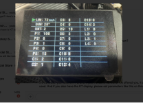
I received this from the bafang retailer I bought the motor from. I don't know what all this is but perhaps you do. These are their perimeters for KT controller and display.
 

Attachments

  • Screenshot 2023-05-20 at 7.20.11 AM.png
    Screenshot 2023-05-20 at 7.20.11 AM.png
    1.4 MB · Views: 1
That was good of them to send you the screenshot. It’s of a KT LCD 08 display and shows all of the parameters on one screen, so you don’t have to scroll through them individually like you do on an KT LCD 03.

I have the following differences:

P3 = 0 so I always have full power available on my throttle.
P5 = 12 I monitor my battery voltage in real time. The disadvantage is the volts can jump around a bit because it’s not sampling over a period of time and therefore not smoothing the displayed value.
C1 = 5 my PAS operated when I back pedalled during testing so I set it to 5 instead of 2 and I didn’t have to mess around swapping the sensor over to the other side of the bottom bracket.
C2 = 0 I don’t know why they have set theirs to 1. Mine works fine with the default setting of 0
C12 = 7 I’m using a 52 volt battery so I set it to the highest value. But even a low voltage cut off at default +1.5v isn’t enough, so my BMS is my safety cut off. But I recharge my battery at 49 volts anyway.
L4 I don’t have this setting on my KT LCD 03 I only have L1, L2 and L3
 
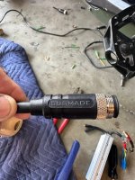
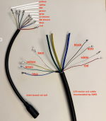
On the motor I needed an extension cable to reach new controllers home. I found this one that matched the plug on the motor but the wire colors seem odd. One is light grey and another is bare wired. Does that seem odd to you? the motor extension cord is made by CUSMADE.
 

Attachments

  • Unknown-1.jpeg
    Unknown-1.jpeg
    73.6 KB · Views: 2
  • IMG_3938.jpg
    IMG_3938.jpg
    65.4 KB · Views: 2
Grin sells motor extension cables. The L1019 cable has extra wires that can be used if you want to add a temperature sensor to your motor. I am assuming your motor came fitted with the L1019. Some Bafang motors have the Z910 connector.

Be careful when choosing a cable, the 3 motor phase wires need to be 12 gauge to handle the current. And even that is a bit on the small side. They get away with having undersized cables on these motors because the insulation they use can handle a higher temperature. Thicker wires won’t fit through the axle.

 
Last edited:
You may be lucky when you combine a KT controller with a Bafang motor and the phase and hall wires are colour matched. So try that combination first.

If it doesn’t work then you are back to trying the various wire combinations to find which one works properly.
I'm back from vacation (Holiday) And thanks to the guy behind me on the plane hacking up a lung I got covid. I'm so glad it didn't hit me until I got home. But this hopefully gives me time to workout the bike wiring this week.
In Paris I saw how bikes are the #1 way to get around. Everyone ride with a super awareness of other riders and cars. Not to mention tourists who aren't use to so many bikes on the dedicated bike paths. Our bike paths here are also pedestrian paths combined. I realized how few bikes we have in the US for daily transportation.

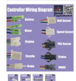
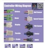
The first question is which wires are the phase? I think they are calling it something different in the attached pic. And at a first glance not all my wires will have matching colors. My cables ends have more colors than the controller has.
My cable ends (Motor & 5 way) cable also use light grey, light brown, dark brown & one bare wire that are not used on the new controller.
Can you let me know what process to tackle first. I've installed the crimp connectors ends on all the wires. So they are ready to go. I'll now install the display and see if the 5 way cable connector for display matchup to the new display. The attached pic is what the controller shows in the online listing.
Thx
 

Attachments

  • Screenshot 2023-06-14 at 8.00.47 AM.png
    Screenshot 2023-06-14 at 8.00.47 AM.png
    416.8 KB · Views: 6
The first question is which wires are the phase? I think they are calling it something different in the attached pic.
"Motor".

And at a first glance not all my wires will have matching colors.
That's pretty common (is uncommon for them to all match).

You can't really go by the colors, you have to go by the signal names/types and voltages. If you don't know what any of those are on the old controller (to then know what they are on the things you're keeping that plugged into it), it's a guessing game and trial and error, which risks damage to both old and new parts.

If you can post everyting you already know about the system as it was before, pictures of the wiring order between all the parts connected to the controller and the controller itself, we might be able to better guess what would connect to the new controller, and what has nothing to connect to, etc.

Remember that on some things like the display, there are both battery voltages and low voltage signal lines. Mixing these up can easily destroy the display and the controller.


I'll now install the display and see if the 5 way cable connector for display matchup to the new display.
Is the display from a different kind of controller? If so it probably isn't compatible with the new one, and you would need to use the display that comes with the new controller. If one didn't come with it you'd probably need to buy the optional one the same seller sells for that specific controller.

(most displays and controllers are not intercompatible; if they can be wired up to turn on, the display won't show speed or other data, and won't change assist levels or settings in the controller).

If it's from the same brand and model of controller it should be compatible and use the same wiring order (but no guarantee of that).
 
First I can't thank you enough advising me. Electronics is absolutely my weakest discipline. So thx.

Im hooking up a new Bafang hub motor to a new controller with matching display. Trying to keep old brake,throtle etc...

Both controller and display are Kunteng and recommended by AGS. My old controller used julet plugs. I was planning on keeping the 5 way cable with julet connectors. But the new display cable was long enough and the pathways holes in the frame was just capable to take the cable (removing the connector/replacing connector after fishing it. It plugs into the controller and wire colors lineup but can I trust the wire colors being that brand is the same and only matching connector? Is it a mistake trying to keep the 5 way cable just so not loose the julet connectors on the handlebar items? Julet connectors are better where they are exposed to water and being snagged.
The other items to hookup are motor, brake sensor, throttle and speed sensor (spoke magnet style).
If the motor is first item to hook up what is the process? AGS said the bafang motor works well with Kunteng controller/display. But clearly not well enough to have a diagram explaining what the wire colors are. Or is there a chart/diagram out there somewhere?
Lastly what's the deal with the bare wire in the motor extension cable? Kinda small if its a ground.
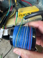
The bare, green, yellow & white wires in the motor cable were wrapped together in some shielding ribbon. I have no idea why so I kept them separate from the other wires incase it matters.
 

Attachments

  • Screenshot 2023-06-15 at 12.12.00 PM.png
    Screenshot 2023-06-15 at 12.12.00 PM.png
    3.3 MB · Views: 11
  • Screenshot 2023-06-14 at 8.00.47 AM.png
    Screenshot 2023-06-14 at 8.00.47 AM.png
    416.8 KB · Views: 7
Im hooking up a new Bafang hub motor to a new controller with matching display. Trying to keep old brake,throtle etc...
Well, if they are matching, then that means the display connector should just plug right into the controller, so that makes that easy.

For an extension cable you then just need to match the wires from one end of the cable to the other, so that the same pin on each end is connected to the matching one on the other end.


Both controller and display are Kunteng and recommended by AGS. My old controller used julet plugs. I was planning on keeping the 5 way cable with julet connectors. But the new display cable was long enough and the pathways holes in the frame was just capable to take the cable (removing the connector/replacing connector after fishing it. It plugs into the controller and wire colors lineup but can I trust the wire colors being that brand is the same and only matching connector?
I don't really know what you mean by that last.

If you are going to cut the connectors off the new controller / display and wire the old connectors onto it, then for anything that connects from new controller to the new display, just make sure each wire from one end to the other goes to the same place it did with the built in connectors.

For any other things that plug into the new controller, if their plugs don't already match wiring with each ohter (or you don't know), you would have to either open both old and new controllers to verify where each wire goes for that device inside the contorller, and use that wire for that signal/power/ground/etc, on each one, or open the device and do that, or experimentally determine, testing for voltages with the old controller and devices to see which wires carry what signals / voltages, so you don't accidentally put high votlages on low voltage cables, or connect grounds to voltage / signal sources, etc.


The other items to hookup are motor, brake sensor, throttle and speed sensor (spoke magnet style).
If the motor is first item to hook up what is the process? AGS said the bafang motor works well with Kunteng controller/display. But clearly not well enough to have a diagram explaining what the wire colors are. Or is there a chart/diagram out there somewhere?

If the KT controller has self learn, then you only need to connect the three phase wires from motor to controller, color irrelevant, and the hall 5v and ground correctly, usually red 5v and black ground, and then the three hall signal wires from motor to controller, color irrelevant, and let the self learn function figure out the order.

If it doesn't have self learn, you would need to manually determine the phase/hall color order by experimentation; there are quite a few posts and threads about phase / hall combo / combination wiring determination, with various methods.

This image
shows two totally different things. You have a data/signal/etc connector, and then you have motor wiring, neither of which will run in the same cable or to the same places. So don't try to connect those togehter. You also can't use that skinny-wire cable for the motor signals. If you need to use a waterproof connector for the motor, use one that has thicker wires for the three phases, or you'll end up melting the insulation on the thin wires used for them if the motor current is typical of such things, and potentially short thigns out and damage the controller.


PAS sensors vary both in type and wiring on controller and sensor. So do throttles for wiring (type is almost always the same). Red usually 5v, ground usually black, third wire usually signal. If there are more than three wires for either of them, you will need more info to wire them up, and possibly have to open a throttle to find out where the wires go inside it as some of them have battery-level stuff in there that you don't want to short to 5v level stuff.


Lastly what's the deal with the bare wire in the motor extension cable? Kinda small if its a ground.
The bare, green, yellow & white wires in the motor cable were wrapped together in some shielding ribbon. I have no idea why so I kept them separate from the other wires incase it matters.
The totally bare wire is a shield ground, connecting a braided shield that separates the signals and their power from the phase wires to minimize interference from teh high current phase signals and help things operate more smoothly. It gets connected to ground at the controller end separately from the 5v's ground (usually black).

A white wire in the motor cable is usually temperature or speed sensor, or both for certain special systems. The KT controllers usually have a place to connect that.
 
Back
Top