Repository for 3D Part Models, Drawings & Schematics

#40 chain is the same pitch and roller diameter as bicycle chain but the width and therefore the sprocket thickness is greater. See here for dimensions: http://www.gizmology.net/sprockets. #40 sprockets are available down to 8t with boss and pilot bore.

#40 is the American standard. 08B is the ISO standard.
 
A shaved width #40 sprocket was my first thought too. The problem is, Bandaro specified a 10mm bore, but the smallest #40 11T off-the-shelf sprockets I could find all had pre-drilled minimum bore diameters of 1/2". I personally don't trust thin section reducing bushings acting as an adaptor in this case, because the set screw/keyway in the sprocket has no torque transferring material directly adjacent to the shaft it's torque coupled to. So then I thought a larger off the shelf bicycle sprocket (no narrowing required) with a 10mm ID freewheel adaptor (if they exist-or if Bandaro got one made) would be less work to adapt than the former option. However If Bandaro is willing to weld the sprocket on then a shaved #40 option with a spacer bushing would probably be easiest, just not so quickly/easily replaced if it needed changing.
 
You can get these in UK:
http://www.technobotsonline.com/sprockets-and-chain/steel-sprockets/tbot-0.5-inch-steel-sprockets.html (Pilot bore 10mm)
The roller diameter for the British standard 1/2" chain is about 0.5mm larger than for #40, though... Probably too much difference......

I seem to remember that Matt had some adapters for freewheels made up. What bore were they?

Staton do adapters with 5/8", 3/4" or 1" bores:
http://www.staton-inc.com/store/products/5_8_ID_Adaptor_for_freewheel_sprockets_1_10_wide_2_set_screws-986-25.html
 
hmmm but technobots dont have 11 tooth unfortunately. I was considering ripping one off a cassette and welding a plate in the middle, but I was hoping to get it machined out, just because it will look a whole lot neater and probably be stronger. Welding onto the axle shaft is not an option unfortunately.

So at risk of being a pain, would it be possible to upload that in a rhino friendly format Miles? it is having an error and i cant even open the pdf as a 2d image on rhino. Or is it just my version thats playing up?

thanks all for the help, there is so much i still need to learn...
 
Here's the model in STEP AP214 format and the drawing as a DXF.
 

Attachments

  • 11t bike chain sprocket.zip
    47.1 KB · Views: 129
  • 11t sprocket 1to1.dxf
    92.4 KB · Views: 122
Binary planet harmonic gearbox
Mostly made from laser cut 3mm steel or stainless plate
I include a pdf drawing and the dxf files for the laser cutters
The triplex chain loop for the harmonic part is 8mm chain - a bit tricky to get hold of
 
Binary planet harmonic gearbox:
modified data, now with:
fewer planets, 8 instead of 12
higher ratio, 19.5:1 instead of 13.5:1
toothed belt(s) drive instead of 6mm chain(s)
NOTE error in sun.dxf - the drawing had 75 teeth instead of 74 - I will repost
 
STEP AP 214 file attached. (other formats? I can't do 3D DXF...)

[Free STEP viewer: http://stpviewer.com/ ]

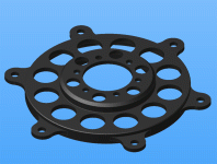
- 6 x 6mm holes on 5-1/4" (133.35mm) diameter circle.
- 4-9/16" (115.89mm) registration diameter.
- 6 x 5mm holes on 44mm diameter circle.
- Weight when made from 6061 Alu. alloy: 92 grams.
 

Attachments

  • Type-1-adaptor.gif
    Type-1-adaptor.gif
    61.7 KB · Views: 6,312
  • Type 1 adaptor.zip
    20.2 KB · Views: 128
awesome work guys, you know your stuff.

Does anybody have a 60t htd pulley for the 5mm pitch? im thinking that would be stronger than epoxy teeth on a disk.

again, any format should be fine, and the #40 chain sprocket above works perfectly.

kk, thanks guys, much appreciated
 
You can download models from SDP, but the tooth profile may not be correct...
https://sdp-si.com/eStore/PartDetail.asp?Opener=Group&PartID=58797&GroupID=217
 
Reserved for the Giant DH comp E-conversion CAD

Credit to Bison_69.

Doc
 
Anybody have exact dimensions or 3d model of front freewheel : http://www.sickbikeparts.com/catalog/product_info.php?cPath=21&products_id=62&osCsid=5qshg3l3qul4l02h01no6j3e11 or any other company front freewheel ?
I am designing front bbracket right now .Thanks !
 
To all E.S. members,

Which gave me so much help on your forum with your technical knowledge; let me now give you in return some open source SolidWorks drawings I have made in the past until now? Those parts are regarding bicycle parts, EV and some electrical components (e-bike)...

Since I have many files... the list would be too long to enumerate then you are welcome to search on this link below (hopefully it works)
http://www.mediafire.com/?595a3424umwdc (Drawings and Torque arm parts have been revised)

I also recommend you using the free SolidWorks viewer: (download and install)
http://www.solidworks.com/sw/support/edrawings/e2_downloadcheck.htm
***Just as a reminder - all those parts must be reviewed for your special need and measurement ***

I won't list the fasteners since they are available and free on the McMaster website (there are many CAD versions over there as well)
http://www.mcmaster.com/#

Special Thanks to DoctorBass and Maxwell65... which inspired me and so many others.

And also all of you genius... devoted members you are very kind to help us (beginners)

SG
 
Hi Guys,

Here is a new link for you... the site is called GrabCAD and offer free sharing 3D files from many drawings softwares.

http://grabcad.com/home

I also discovered lately a very nice application for universal rendering called KeyShot... very easy to use and outstanding finish effects.
http://www.keyshot.com/ (easy to find for free on the web)

I am now a GrabCAD member and I have uploaded many files over there... http://grabcad.com/sg/projects

Have a good day!...
 
How to draw a chain sprocket
to make a dxf file to take to the laser cutters, for example -
might save someone the trouble of looking it all up....
 

Attachments

  • Drawing a chain sprocket.doc
    4.7 MB · Views: 322
There are also some free programs out there that will do it for you. At least one of them even draws in the mounting holes at standard or custom BCDs. I cannot ATM remember the names of them, though I recall finding them easily with a google search some time ago.
 
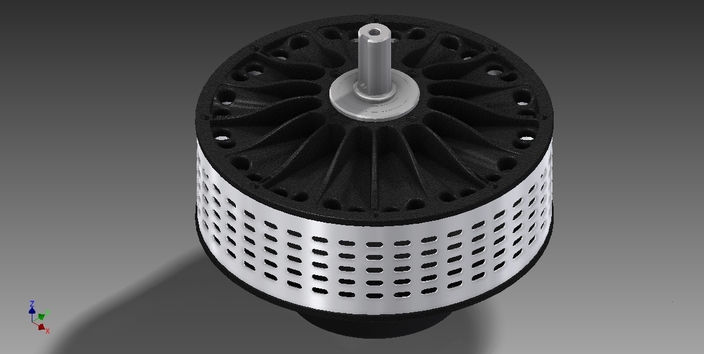
Ref: http://grabcad.com/library/agni-motor-95r

medium.jpg
 
If, for some odd reason, anyone with a Gotham Citizen 2 wants my torque arm file AND simultaneously finds this post,

I've been using a torque arm made of 5/8" O1 steel on both sides (decided on not hardening it, so as not to be so much harder than the axle.) There's ample leftover threadroom. The file could be *slightly* better by moving the hole down closer to the edge by a fraction of an inch. Also, you could cut a hundredth of an inch from the axle diameter, but right now it's at .393", and that's pretty decent. Plot-print and see for yourself. Works fine though. The nut whole is 6m x 1 (METRIC). My hole in the torque arm file is slightly oversized.

I use file format IPT, but these files are the converted IGS and STEP, which I believe to be wholly accurate, but yeah, be diligent and double check the file yourself.


I should add that on one side the torque arm has a triangle 2mm tall maybe 8mm long overhanging. This is because the dropout piece is slightly wider on one side, and I originally made a file for each side. I am only posting the file I actually used, which I ended up flipping for the opposite side. If your weld is exceptionally wide, then you might need to grind the edge a tiny tiny bit because I found one of the dropouts to have a slightly wider weld. The torque arm was originally made with epoxy in mind (hence, large surface area), but I added the bolt hole in the last second, because the bike already has a threaded hole there, so you may as well use it. You probably want ~13mm bolt, depending on how thick your bolt washer is. (a 6Mx1 bolt, of course.)
 
The files for the Turnigy 80-100 motor appear to be corrupt on the server, could someone that has the model working in autodesk inventor post a new copy?

Thanks,
Andrew
 
Back
Top