Rewinding a 15470 outrunner

It will help a bit. The stator losses are primarily due to the fundamental frequency but also the harmonics have an impact. Thing is, these motors have innate horrible harmonics and can be a pain in the arse to drive with FOC. I've been trying recently and have had some success but the noise is still serious because of the back EMF harmonics.

I've never been too concerned about 20s, 24s... Batteries. They tingle if you touch them but I've never managed anything that actually hurts. Regulatory is another issue that needs examining per the standards.

Dropping to 20s allows you to go with 100V FETs which generally have far better on resistances.
 
I've never been too concerned about 20s, 24s... Batteries. They tingle if you touch them but I've never managed anything that actually hurts. Regulatory is another issue that needs examining per the standards.

I haven't really looked into what standards might be applicable, I did come across BS EN 50604-1:2016 but im not sure if its aimed more at cars.

After some playing around on solidworks I came to the conclusion I was going to rewire the motor with a single thick strand. Mainly because with the parallel star arrangement I came up with I thought it would be easier when making all the interconnections.

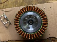
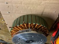
After some effort and a couple of blisters, I have managed to wind the motor with 1.6mm, which gives me 2mm cross section compared with the 1.6mm previous. (probably less than 1.6mm if you took into account the enamel thickness)

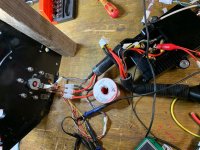
I have connected all the star points, I just need to connect the phases.

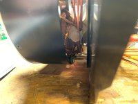
rewind 1.jpg

rewind 2.jpg
 
I doubt the fill is that high if you consider all the area in the slot, I will work it out at some point. It would be possible to wind this motor with 1.8mm, I reckon that would be maximum possible fill at 2.5mm2. I did wind 3 slots with this, but I decided it was pushing my look to much. So I took it off and ordered the next gauge smaller.

Im looking forward to seeing how it performs. Hopefully everything is correct and it will turn at the expected KV.
 
1.6mm is 14 AWG wire.

That was heroic.

And blisters are to be expected when you get to the thick wires.

The motor itself is physically capable of more room than the smaller RC level brushless motors which I had real troubles even at 20 AWG or 18 AWG and only achieved success with 26 AWG which is like butter to wind with.

Where you get into troubles with the thin wires is you need so many of them the potential of getting things tangled up is very serious.

Great work !!!

----------------------

https://www.windings.com/technical-reference/slot-fill-and-design-for-manufacturability/

As slot fill percentages increase, so do time and labor costs. Among manufacturers, a percentage of 60 to 70 is considered standard. Stators with slot fill percentages of 70 to 80 percent are more challenging to build and may require specialized tooling. Above 80 percent is very difficult; inserting all the components without damaging the wire or its insulation requires custom tools and fixtures, and may take up to three times as long or longer to manufacture than lower slot fill designs.
 
Just had the motor running for a small test. I have found that it runs lovely backwards, but is lumpy in the direction I need. Is this the point where someone says I have wound it the wrong way? I did think about this, but I decided it wouldnt make a difference....... that being said, moving the sensors around doesnt seem to solve the issue.

I am thinking I should maybe chance the physical order of the sensors and then swap the phases around to suit and see if that helps.

I am sure from the past of playing around with a 120100, it would run fine in both directions with external sensors.

Another possible cause would be the sensors, they use to be aligned with the slots, but now they are not. I wounder if the stator magnetism is interfering with them. Although I wouldnt expect this to be an issue when its only turning at 10 RPM.
 
If it runs well one way, it should the other.

Iirc you've converted from Delta to star. That explains the hall sensor shift.

There are combinations when wiring up either that result in poor running. You have made sure the phases are the correct way round right? It's possible to connect them such that they are 0, 60, 120 degrees rather than 0,120,240 degrees.

It's also quite possible the halls do indeed need swapping.

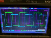
This might be best approached with an oscilloscope.
 
As it was getting late last night I left it with the intention of having another look this evening.

I am fairly certain the issue is with the hole sensors. I was reading the magnets on the back side of the 15470 and the system no longer works as well. One reason being the thicker windings and not getting in the way so my PCB cant be as close, the other being the sensors are no longer directly inline with the slots.

What I noticed after posting last night was if I spin the motor by hand, once I get over 100 RPM the encoder and hall sensors are not longer reading the same RPM. I guess that the stator tooth they are close to is now also switching them.

It might be that when the motor is spinning one way, the stator interferes with the sensors less than when its turning the other.......

So my current thought process is that we need a better sensor system, yes I could stick to delta and it might work as it was before, but I cant help think its to marginal.

I'm guessing at this point some people will be shouting absolute encoder, but my speed controller doesnt support this and I do like how simple the sensors are. No need to start doing encoder offset tunes......

I have used photo interrupters before, so something along these lines could work. But the smaller I go in diameter, the more manufacturing tolerances will affect the accuracy. I don't think there is any viable way of using hall sensors, I reckon this only works for delta with the sensors in the middle of the slots.
 
Sure you can make the halls work but it might take some iterations. Try swapping the hall/phase combinations around first

Then you can use less or more sensitive sensors/move them outside of the motor with separate switching magnets or magnet ring/grind sensor slots in the laminations in the correct location/offset them to one side of the slots/try filtering the signals if they’re noisy/move them closer or further from the rotor/ etc.

Buut once you’re sure you’ve run into sensor issues that seem really complicated it makes more sense to use an outside encoder. Perfect switching, no signal noise etc.
 
Well, I have had another look at it tonight and my current conclusion is that it just does not like turning the way I need. The hall sensors are reading ok, I have tried swapping them around and swapping around the phases, changing the alignment but everytime I find a backwards rotation it runs fine, everytime I find a forwards its lumpy.

The motor turns by hand smoothly in both directions, if I short all phases together it turns slowly, but smoothly when forced round by hand. I just cant see what the problem is at the moment.

I would be interested to know why the sensor alignment shifts between star and delta, and also if the 30 degree shift is direction dependent.

I currently have only tried swapping the hall sensor order once, as a wire snapped off and my crimping tool is at work, I will try swapping this around some more tomorrow night.
 
Would be interesting with a video with sound that shows the difference between front/rear driving.

I assume that it is the hall sensor postion being shifted being the issue, normally it can be advanced about 30degs electrical without too much issue but not retarded 30degs. Therefore i’d find a new sensor location for your running direction that’s advanced between 30-60 degrees electrical from where they are now and try again.

It’d be beneficial to get a scope, there are these mini scopes that you can buy for less than 100eur that i’ve seen used here with ok results, then you’re not working blindly anymore.
 
I have got a scope four channel scope, i forgot to bring it home from work yesterday. If I can find all my scope leads I will clip all three channels to see exactly what is going on.

The hall sensors I used are latching, I can adjust them a full stator slot either way. They are however quite a distance from the magnet and they pick up on the magnet ends. They are like 4mm off, I need to come up with a way off packing them off the pcb, but they are surface mount devices. I looked for a through hole sensor that detected on the end rather than side, but I couldn’t find anything.

I will make a video so you can see how it looks. Hopefully I will get enough time to have a proper look at it on Saturday morning.
 
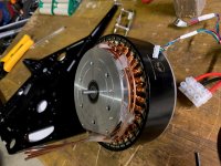
Slight delay on this post, but finally got around to it. Below are some pictures to show you the setup.
5.jpg
6.jpg
7.jpg
8.jpg

So, after some head scratching I realized that the rough running was down to my own control loop. In reverse it wasnt active so thats why it ran ok like this. I knew that it needed setting up for the new KV, so was running at a low voltage to kind of get around this, however the fact was it made the gain to high when the motor was turning slowly. As soon as I turned the correction off it ran perfectly. I also managed to get the sensors located better and found that with the motor running the correct way they are not far off being inline with the slots which is good. So I am now less worried about them.

I have had the motor up to speed on 100V and its spinning at exactly 5400RPM. So that has worked out well.

9 turns in delta original, wound 2.5turns in star.

I have just done a really basic torque test, as I did this some time ago with the motor before its rewind. The results are not really as expected. Basically the test was done on my 3A bench power supply at 100V, it was a measure of how much torque it could make at 3A using a spring balance. The results I have found are that I cant really see a difference before and after the rewind. At a 200mm lever length in both cases it just managed to pull 25lb. So I dunno.

I have also tried it on a 7A 100V supply and it managed 35lb at 200mm. I am not sure what the exact current was and it jumps up in steps so it hard to know if its almost ready to jump to the next one. It just a rough idea. I believe this converts to 32Nm, so through a 10:1 ratio that is 320Nm on the rear wheel at 700W. That sounds like a lot?

I am not going to test it on any more current locked rotor as I would need to make a better setup and I once overheated a speed controller doing this in the past. Its also not a very good test as the peak torque varies with segment position.

My target was 750Nm max at the rear wheel as this is what an electric motion trials bike claims to have.
 
Back
Top