Street legal Cafe Racer build.

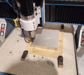
Setting aside the frustrations of procurement, I finally got to cut some metal today!
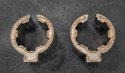
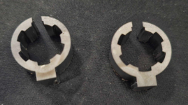
View attachment 345920View attachment 345921View attachment 345922

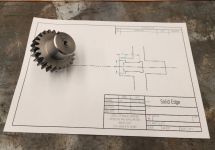
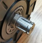
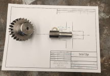
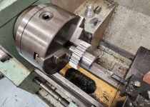
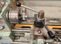
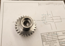
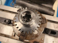
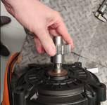
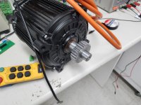
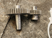
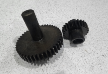
These are the roughed (except for the gear ODs which are to final size) out blanks for the gears. The input shaft is a larger diameter because I'm going to cut an internal spline in it so the output shaft of the QS180 will slide inside. This will make mounting the motor to the gear reducer easier.

I've made them out of E110 with a view to case hardening them. Man that is a tough alloy. My little lathe worked hard to turn the big (112.5mm) blank!

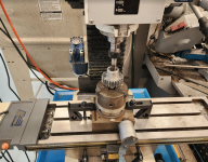
I'm going to try to cut the teeth before I have to travel in a weeks time.
Really enjoying following your progress! I'm looking to find a way to mount a Gates pulley to the QS180 shaft, I'm getting some steel interfaces cut that will sit between a pulley taper bushing and the shaft, though not sure if this will be the best approach, sendcutsend are unable to accurately cut the thin geometry in 0.5" steel so getting 0.125 and .250 and seeing if they'll stack. Do you know what profile the QS180 shaft has? I'm trying to see if it's the same as any vehicle sprockets, and maybe I can find a pre made coupling that will fit straight on the QS180 shaft.
 

Attachments

  • unnamed-1.png
    unnamed-1.png
    259.3 KB · Views: 10
  • unnamed.png
    unnamed.png
    280.3 KB · Views: 10
Last edited:
Really enjoying following your progress! I'm looking to find a way to mount a Gates pulley to the QS180 shaft, I'm getting some steel interfaces cut that will sit between a pulley taper bushing and the shaft, though not sure if this will be the best approach, sendcutsend are unable to accurately cut the thin geometry in 0.5" steel so getting 0.125 and .250 and seeing if they'll stack. Do you know what profile the QS180 shaft has? I'm trying to see if it's the same as any vehicle sprockets, and maybe I can find a pre made coupling that will fit straight on the QS180 shaft.
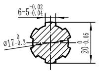
Spline Shaft 17-20 5mm Teeth.jpg
That's the motor shaft cross section. It's a simple spline to cut.
Get a local machine shop to cut it in a flanged hub, then bore the pulley to take the hub. Bolts through the flange to transmit the torque.
 
View attachment 346930
That's the motor shaft cross section. It's a simple spline to cut.
Get a local machine shop to cut it in a flanged hub, then bore the pulley to take the hub. Bolts through the flange to transmit the torque.
Thanks, sounds promising, I’d thought it maybe complicated and expensive to cut (based on zero to no real experience!) my measurements were way off also, I had the inner diameter at 16 and the spine width at 5mm, appreciate the help!
 
After two weeks away, I was keen to get back into the build, sadly a bunch of work has followed me home so it'll be slow progress for another week or so.


Still I took some time off today to prepare the small gear for cutting the splines that will engage the motor. This has to be done before I harden the thing.
splinerough1.png
There's a shoulder on the outside, then the splined section then a relief cut to allow the tool that cuts the spline to bottom out.
A reminder of what the motor shaft looks like:
Spline Shaft Pic.jpg

The first thing to do was to make a plug gauge up to measure the 17mm bore, it's 40mm deep so there's no getting calipers in there.
splinerough2.png

Then just some careful turning at high speed with a sharp tool
SPLINEROUGH3.png
Sadly the pic isn't as sharp.

That took care of the 17mmbore and 25mm step.

Sadly my nice ID grooving tool just wasn't going to get down that 17mm hole, so I had to grind one up.
splinerough4.png

The last op was to chamfer the outside end of the section to be splined to help the tool get started.
splinerough5.png

If you squint, you can see all of the features cut
splinerough6.png

I'm pretty happy with the tolerances.

 
Nothing for it, just got to cut those splines. I'm a bit nervous about this because it's not something I do a lot so I'm not well set up for it.
Screenshot 2024-02-13 110817.pngScreenshot 2024-02-13 110744.pngScreenshot 2024-02-13 110806.png

I'm about half way through the job, it's slow and quite hard work cutting around 0.05mm per manual stroke.
I'm quite surprised that there isn't a lot of taper top to bottom (about 0.06mm) . I guess the setup is reasonably rigid.
Fingers crossed!
 
Screenshot 2024-02-13 130002.png
aaand it doesn't fit.:(

The diameters look good. I'm pretty sure there's some rotational error in the slots and not enough clearance to cover it.
I only left 0.05mm clearance on the slot width. I was shooting for 0.1mm but over ground the tool.
I'll widen them another 0.1mm and see what happens.
 
Very nice machine work.

That fuse is absolutely massive. Thought these are neat and compact. I'm building a pack with 650 amp burst and a QS180 so I went a little lower than the 500A option. 16ka interrupt so should be suitable unless I'm missing something.

I think a belt drive is the logical conclusion for these EV conversions, at least for those who are not running a driveshaft. Chain lube makes a mess.
Yeah, but they only go to 500A, I need >1000A, and 125V is right on the limit for voltage. If you pop a fuse, there's going to be a big back EMF kick which might arc over.
 
Yeah, but they only go to 500A, I need >1000A, and 125V is right on the limit for voltage. If you pop a fuse, there's going to be a big back EMF kick which might arc over.
Fuse would need to see 1000A for 60s. Not sure where you're going to be able to hold a throttle open that long and I'm doubtful the qs180 wouldn't become the fuse in that scenario.

This is to say an EV fuse would likely never be tripped by your use case even at 500A rating, while tripping faster should it ever need to do it's job.
 
Last edited:
Fuse would need to see 1000A for 60s. Not sure where you're going to be able to hold a throttle open that long and I'm doubtful the qs180 wouldn't become the fuse in that scenario.
Fuses aren't there to protect you against your wrist. That's what the limits in the controller are for. A fuse protects the cables that are downstream from fire if there is a fault. In my case my battery has a rated continuous discharge rate of 950A (22P or 23P), it'll do a LOT more than that if something shorts. The cables are 95mm^2 and only about 1m long. That fuse will blow pretty quick.
The body controller will also poll the drive for current and open the contactor if we get into trouble. I have some 1000A hall sensors too. I may yet wire them in as a backup.
 
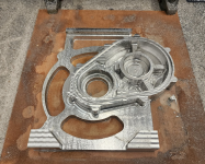
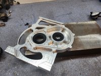
After endless fit ups and measuring, the gearcase design is as close as it's going to get.
Time to start work on the toolpaths....

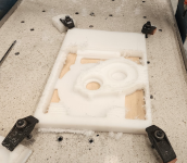
Today I tested most of the path for the front side of it in some HDPE.

Lots to tweak before it cuts metal, but it came out pretty good for a first run.
Screenshot 2024-02-19 125934.png
 
Nice :)
I must say I am jealous of your machines and knowledge how to use them.
I had problems even find someone willing to make a spliened shaft for me, it would sure be nice to be able to do it myself.
Don't be daunted by it. What you're seeing is just "OK, this year I'm going to get 1 new piece of gear and learn how to use it". Repeated 30 times.
If you plan this process right, and take on projects (like this one) that push you to learn new things, you'll be surprised how quickly your capability to make stuff grows....
Remember: Everything is made by someone, why shouldn't it be you?
 
Not the sort of thing you'd expect to see in an ebike build thread I guess...
air hammer.png
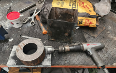
Here, I'm pulverising BBQ fuel with an air hammer to make a source of carbon for case hardening the gears....
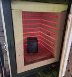
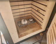
It took a while, but a buddy found a furnace big enough to do the job.

In other news, I've given up on Far-driver. It's clear to me that their 108V drives are vapor-ware.

From the head of international sales at the company:

"fardriver produced 108V products in small batches last year, so we sell this product again. However, this product has certain defects, so we stopped the shipment of this product at the end of last year, and have been testing the new product, but the effect is not very good."

Would have been nice if he'd told me that early december when I gave him USD2000 for 1081800....
I've asked for my money back and ordered a 3Shul CL1400.
On one hand, I'm a little worried because there just aren't a lot of them out there yet. On the other hand, they are rated for 30S and have lots of comms options....3Shul Motors have quoted 30 days lead time... Let's see..

Oh, and I FINALLY got my permit to modify the bike, a brisk 3 months after I applied!🤦‍♂️
 
OK, so it's been a while.
Some of the delay has been caused by work, which just went nuts, but I've spent a LOT of time tracking down some help with case hardening the gears. It seems that furnaces big enough are a bit hard to come by in my neck of the woods. A big thanks to Martin and Bill for helping out...

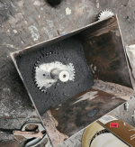
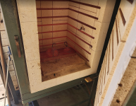
So the process starts with smashing up a bunch of BBQ briquettes, mixing in a little sodium carbonate and packing it in around the gears in a steel box.
Screenshot 2024-04-12 170213.png

This then gets sealed up with some clay
Screenshot 2024-04-12 170441.png

and baked at 930 deg C for a few hours.
Screenshot 2024-04-12 170518.png

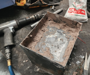
They come out still soft, but with the top mm or so of the steel having a high carbon content.
Screenshot 2024-04-12 170716.png

The next step is to machine away metal from any area we don't want to be hardened.

Screenshot 2024-04-12 170826.png

I don't want the flanks hard because its a large area and I'm worried about cracking when I quench them. I also took the opportunity to bring the shafts down to grinding tolerances (ie +0.15mm-0.2mm ).

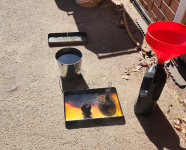
Then they got fluxed up to try to prevent scale forming on the teeth, and it was back to the furnace for a trip to 850C, followed by a dunk in some oil.
Screenshot 2024-04-12 165112.png
Screenshot 2024-04-12 165122.png
Screenshot 2024-04-12 165130.png
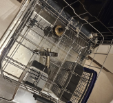
At this stage they were covered in a lot of molten flux, polymerised oil, and other assorted nastiness and this stuff was proving hard to get off... Until I remembered that the flux was boric acid.... Into the dishwasher they went!
Screenshot 2024-04-12 165138.png

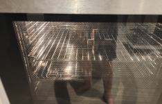
After that they were clean enough (just some of the hardened oil left) that I was comfortable stress relieving them in the oven at 250C for 3 hours.
Screenshot 2024-04-12 165146.png

There was tiny bit of oil smell, but it wasn't too bad.

I sand blasted the flanks of the gears, partially to finish the clean up, and partially to further stress relieve the surfaces. and they came out pretty good I reckon.
Screenshot 2024-04-12 165155.png

This afternoon I started the very careful process of grinding the bearing seats. Lots of dial gauge setups and triple checking.
So far I have two of the 4 ground to between +0.015mm and +0.02mm which will give me a light press fit.


In other news, I FINALLY got my money back from Jack at Far-Driver. Seriously folks, don't deal with this guy! He compulsively lies and it took me promising him I'd pay him a visit on my next trip to China to get him to refund my money.

On the plus side DHL tell me that I'll get a Gen 4 CL1400 drive next week!

Big post, hope y'all made it through! :)
 
Me: I could really use a primary reduction for my moped build, but none of the gears that are available to buy will work for my application. I guess I can't use any.

This guy:
index.jpg
 
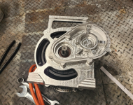
Got a bit more done this morning.
Finished grinding the bearing seats on the gear shafts and turned up some delrin bearing simulators (just bushes that are slightly oversize on the ID).

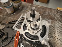
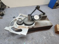
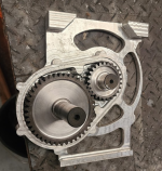
This let me put everything into the front half of the case and check mesh, run out, etc...
1000008441.jpg1000008440.jpg
And the gears were binding up! I spent ages trying to figure out why. I knew that the mesh was on the tight side (about 100um clearance) but I've been careful to keep run out well below that in all my set ups.

Not having a surface plate, height gauge and some ground v blocks meant it was hard to get good measurements of tooth height. Worse still the binding seemed to happen at random points. Not periodically as I would have expected.

Finally I realised that, prior to hardening, I had turned the gears to a thickness of 20mm and had forgotten to deburr one side of one of them. It was the random burrs that were causing the binding! 10 min with a diamond wheel in the Dremel and it was turning like silk....
 
Last edited:
Oh, and 3shul confirmed that the CL1400 will run fine on a 30s pack, even with regen. So I can now finalise the battery design.
 
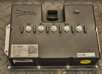
Well, after only 4 months and no end of drama, I finally have a controller.
Controller.png
Drives in this spec range are like hens teeth!
 
Back
Top