strong vibration and noise from motor?

Joined
Apr 29, 2012
Messages
32
I just tried to go out for a ride, but there is something wrong! the motor is making a lot of noise, the whole bike vibrates strongly when i turn throttle, and motor keeps cutting off too!
Day before yesterday everything seemed to work just fine!
The vibration is quite strong, feels a bit like holding a small hammer-drill. I also notice motor shuts down while the throttle half open, but restarts if i turn the throttle a bit less or more.
Freewheels ok. Voltage seems steady. Had it inside the house, so it cant have gotten wet or anything..

Any help?

I took video and put it publicly available here:
https://dl.dropbox.com/u/74658243/IMG_0646.MOV
 
It does sound like a dodgy Hall sensor to me. A Hall failure or loose Hall or phase connection can produce this symptom.

Best bet would be to check the connections, then test all three Hall sensor outputs to make sure they are OK. The Hall sensors need a pull up resistor to between +5 and +12 V if you're going to test the hub disconnected from the controller, then you can use a meter to check that each one is switching as you turn the wheel. The easy way to do this test is one of the little Chinese test boxes, with LEDs for the Hall outputs.
 
You got a loose plug. Could be a hall or a phase. Look hard for contacts backed out of the housing.
 
Jeremy Harris said:
Best bet would be to check the connections, then test all three Hall sensor outputs to make sure they are OK. The Hall sensors need a pull up resistor to between +5 and +12 V if you're going to test the hub disconnected from the controller, then you can use a meter to check that each one is switching as you turn the wheel. The easy way to do this test is one of the little Chinese test boxes, with LEDs for the Hall outputs.

I have no idea what that means or what you're talking about! :oops: I think Hall sensors are something that are inside motor and have something to do with making the motor run. Spesifically when to power which magnets i think. How to test it i dont know. I have a general purpose volt/amp meter but i dont really know how to use it to measure this? I did try, but the meter's wires got really hot and so i decided it best to abandon my blind efforts... Just a few days ago i was happy with myself when i got the battery voltages measured! :roll:

dogman said:
You got a loose plug. Could be a hall or a phase. Look hard for contacts backed out of the housing.

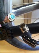
I have these 2 wires going into the motor from the controller. I suspect the thicker is power and the smaller are for control? They seem well in place as far as i can see. I bent the contact plates on the 3-wire plug to more pronounced position to make sure there is no contact problem. (I had that problem with battery harness wiring and that fixed it)

I dont know what to do with the smaller one. It seems i have to break it or cut the wires to look inside? I dont see a way to open it... Then i suppose i could just cut the plugs away and solder the wires together to eliminate any chance of contact problem, but that's not really the prettiest and most practical solution, since then motor and controller are soldered together...

IMG_0648.JPG

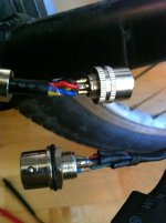
I got it open and can now see the solderwork, it seems solid, no wires are touching eachother and everything seems well connected to me atleast
So... What to do??

IMG_0650.JPG
 
OK the plug you took apart is the Hall sensor connector. The red wire should have around 5V on it, the black wire will be 0V and the yellow, blue and green wires are the outputs from the Hall sensor.

If you are very careful not to short anything, you can test the Hall sensors like this.

1. Connect the Hall sensor connector to the controller, but for safeties sake leave the three way phase connector disconnected.

2. With the back off the Hall connector (as in your photo), carefully connect the meter on the volt range between the black wire and the yellow wire. Make sure your meter probes don't short any of the connections.

3. Turn on the power to the controller and don't touch the throttle.

4. Rotate the wheel slowly by hand (or get someone else to rotate it if you're holding the meter probes steady) and you should see the voltage on the meter switch from 0V to about +5 V several times as the wheel rotates. If it does, then it means the Hall sensor on the yellow wire is working OK.

5. Repeat this test for the blue wire and the green wire. If all three wires show a switching voltage as the wheel is turned then you know that the Hall sensors are working OK. This means the problem will be somewhere else and we need to think again.
 
A few days ago we changed the forks on a bike with a 250w motor, and when we put it all back together, it had exactly the problem you described. We checked all the connections and they all seemed ok, but the problem remained. Out of frustration I spun the wheel by hand while it was vibrating, and then it started spinning normally, and it's been OK ever since.
Might be worth a try!
 
d8veh, I tried but sadly no success..

Jeremy, I measured the wires as you instructed (took a while as i needed to buy a new meter because the previous melted a probe and turned black with a bright flash as i was measuring battery voltage, im still not sure what i did wrong! :roll: Wife was not happy and told me to go play outside! :lol: ) Anyway, here data;
- black-red gives 4,35V
- black-yellow gives 4,9V and switches as the wheel turns
- black-blue gives 3,35V and is constant as the wheel turns
- black-green gives 5V and switches as the wheel turns

I double measured from both sides of the plug and i got the same results, thus ruling out faulty plug.

So, blue is the quilty one!
What should i do next ??
 
It occured to me that having ~82volts and 50 amps might be too much and so maybe i have burned/melted something inside the motor.

So, opened the motor to have a look inside. Searched and found a good guide on opening a hubmotor here:
http://endless-sphere.com/forums/viewtopic.php?f=14&t=30211&p=436758

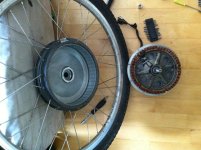
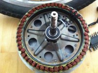
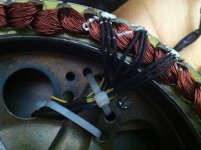
And here's how the motor looks taken apart.
IMG_0651.JPG
IMG_0652.JPG
IMG_0653.JPG
Looks pretty ok to me, no smoke, no melted things, no blackened parts or anything... but hey, what do i know...

How should i proceed? I want to go for a ride!!
 
Black blue not switching, sounds like that's the hall sensor you need to replace.

Too bad it wasn't as easy as locating the bad contact in the plug. It coulda been that. A wire broken at the plug solder, or whatnot. The big plug, the andersons are notorious for contacts backing out of the plug housing.
 
ebike-infected said:
d8veh, I tried but sadly no success..

Jeremy, I measured the wires as you instructed (took a while as i needed to buy a new meter because the previous melted a probe and turned black with a bright flash as i was measuring battery voltage, im still not sure what i did wrong! :roll: Wife was not happy and told me to go play outside! :lol: ) Anyway, here data;
- black-red gives 4,35V
- black-yellow gives 4,9V and switches as the wheel turns
- black-blue gives 3,35V and is constant as the wheel turns
- black-green gives 5V and switches as the wheel turns

I double measured from both sides of the plug and i got the same results, thus ruling out faulty plug.

So, blue is the quilty one!
What should i do next ??

Yes, you've found the problem. Congratulations!

To fix it you need to take the hub apart, unfortunately, as it's either a duff connection inside the motor to the blue Hall, or it's the Hall sensor itself that's failed. Replacing them is reasonably straightforward, the hardest part is taking the motor apart. The sensors are fairly cheap, the Honeywell SS411 is a good replacement.
 
Thanks so much everyone for helping me out here!

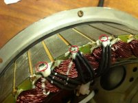
Okay so I need to change 1 hall sensor. They are these things here, right? The small metally things inside and between the magnetplates. They are very small, like maybe 2-3mm.
Covered in some white siliconlike substance. (Funny thing I found is that inside the motor there are wooden sticks between the e-magnets. Thats pretty cool :lol: )

IMG_0654.JPG
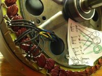
I opened the bindies holding the wires tight, and had a closer look at the wiring trying to determine which one is the black-blue-hall-sensor. I Have no idea! ...Made a note of which wire goes where too..

IMG_0657.JPG
I have no idea which sensor is the broken one, so I guess I could just change them all...
Do I just violently pry them away with, a screwdriver for example? Or is there a sophisticated method to doing this? Heatgun? Im sure this is routine to many of you here?
Are these hall sensors something I can get in general electronics shop tomorrow? Or do i need to order it from somewhere and wait a week? If so, any recommendations EU area?

I was also thinking how to test which one of the hall sensors it is. Im thinking problem could still be the wiring between the hall and the plug!
If I hook the motor to the controller, like before, without the thicker phasewires. Peel away the white stuff and heatshrink enough to probe the connections, and then move a magnet over the sensors, shouldnt I be able to measure from voltage, which hall is faulty?
 
Today i got a mail package with hall sensors that I ordered from mr Lyen. I easily recommend his services to anyone, all was smooth and quick and customer friendly. I also bought the tester for future needs (http://endless-sphere.com/forums/viewtopic.php?f=31&t=20413#p297852) and a torque arm, which sadly did not work for my dropout. No matter, I already have one that works, and further down the road I could get this one working too, it just needs a little bit modifying.

So, I decided to switch all 3 hall sensors. Did so, that was fairly easy, then put the motor back into one piece and YES! It goes nicely again! Was just out doing a small testride :)

It was surprisingly difficult to put the motor back together, much more so than taking it apart. But after a little sweating I managed to get the motor centered well enough to not make any scratchy noises when the wheel turns.

I found these links helpful: (and a bunch of others too, but lost links to them)
http://www.electricbicyclesmagazine.com/hallsensors-page1.html
http://endless-sphere.com/forums/viewtopic.php?f=16&t=3720

Things i consider worth noting;
- great thing i took pic of the hall wiring before i cut the wiring and removed the old halls. Without the pic and notes, I would have been in trouble! Especially since the colorcoding of my hall wiring was somewhat confusing.
- great thing i marked the position of the lid in comparison with the motor before taking the lid off the motor, as without this I would prolly have spent a lot more time trying to get the thing not scratching!
- great thing i was cautious when putting the motor together, chance to get my fingers bloodied was obviously present. Those magnets are pretty strong!

I feel happy to ride again, and happy that I managed to fix the problem, and happy i learned a lot while doing so!

Thanks again! You made my day!
 
Great job!

Really glad to hear you got it working again.
 
Jeremy Harris said:
It does sound like a dodgy Hall sensor to me. A Hall failure or loose Hall or phase connection can produce this symptom.

Best bet would be to check the connections, then test all three Hall sensor outputs to make sure they are OK. The Hall sensors need a pull up resistor to between +5 and +12 V if you're going to test the hub disconnected from the controller, then you can use a meter to check that each one is switching as you turn the wheel. The easy way to do this test is one of the little Chinese test boxes, with LEDs for the Hall outputs.
Yeah bro this guy is the man right here props 4 all ur replies u have helped us all out.
 
Back
Top