
You are using an out of date browser. It may not display this or other websites correctly.
You should upgrade or use an alternative browser.
You should upgrade or use an alternative browser.
Sur-Ron - New Mid drive Bike
- Thread starter Allex
- Start date
X-Nitro
10 W
:lol:
owhite
100 W
- Joined
- Aug 3, 2020
- Messages
- 285
Can anyone shout out the dropout width of the surron bikes?
I saw some aftermarket axles and they looked around 190mm but getting an exact number would be helpful.
I apologize if this is a naive question, or if there's different dropouts for the light bee or something.
I'm asking because I'm starting design of a custom bike and there are aftermarket surron hubs that seem promising.
X-Nitro
10 W
I have the the new SMPro platinum rear hub here showing 133mm between spacer flanges, add 10mm for the brake anchor, another maybe 20mm each side to get thru the swingarm & chain adjusters. The spacer bore is 12mm.
owhite
100 W
- Joined
- Aug 3, 2020
- Messages
- 285
X-Nitro said:I have the the new SMPro platinum rear hub here showing 133mm between spacer flanges, add 10mm for the brake anchor, another maybe 20mm each side to get thru the swingarm & chain adjusters. The spacer bore is 12mm.
Thanks for replying -- the bolts at this link are 163mm without thread. If I interpret your statement correctly, your hub is 133mm, plus (20+20+10) which gets me to 183. So my guess is somewhere between 163 and 183...still on the hunt for the most accurate number.
X-Nitro
10 W
Ok keep looking, but I'm not sure why you think axle thread or shoulder length specifies other dimensions.
I use the long axle and have 5mm thread extending clear. The combination of NTC disc guard and fat hub floating rotor requires an addnl 3mm spacer on the axle to clear button head disc mount bolts, bad on ntc design.

I use the long axle and have 5mm thread extending clear. The combination of NTC disc guard and fat hub floating rotor requires an addnl 3mm spacer on the axle to clear button head disc mount bolts, bad on ntc design.
Rix
100 TW
X-Nitro said:Ok keep looking, but I'm not sure why you think axle thread or shoulder length specifies other dimensions.
I use the long axle and have 5mm thread extending clear. The combination of NTC disc guard and fat hub floating rotor requires an addnl 3mm spacer on the axle to clear button head disc mount bolts, bad on ntc design.
discnguard2.JPG
Nice fin, looks trick!
X-Nitro
10 W
Hawaiiguy said:I have that disc guard and rotor,did you use the supplied disc screws( there purple),my friend reused the stock disc screws and had clearance problems,put on the supplied screws no problem.
And what supplied screws would those be? The special ones now shipped because I raised hell??
Such a crappy way to fix a clear design flaw. There is no reason on this planet that material needs to exist in close proximity to the bolts, lots of room on the other side, an idiot could see this. The original part even has a clearance channel, kind of a hint eh?
X-Nitro
10 W
Rix said:Nice fin, looks trick!
Thanks, disc fins are a basic element of dirt-biking.
Talaria needs to take notes here, we will see if they can respond by building the part right in the first place.
I like the strength the ntc guard has but;
These guys make a fancy-looking guard, I hope they get their re-design part shipping soon.
https://www.warp9racing.com/product/surron-rear-disk-guard/
X-Nitro
10 W
Hawaiiguy said:Mine and my friends came with low profile purple screws that have clearance.My friend originally reused his stock bolts and had the same clearance problem.Both of our Luna rotor kits had the purple screws included .
That's nice, to date luna has supplied me with 0, that is zero, fasteners for the installation of the disc set.
They were unaware of this problem when I bought my set.
I had to solve the problem myself.
")
Hi folks, I hope anybody of you can help me.
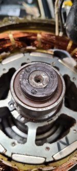
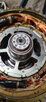
My hall sensor magnet seems to be faulty. The magnet has slippet up in to the Hall Sensor. I have fixed the magnet with Loctite on the right postion again and i replaced the Hall Sensor with a new one. But i got the motor not running.
My Nucular can not find the right Hall sensor position. I have testet it with 3 Led's on the Sensors Output. The sequence of switching is not what it should be. On one Position all 3 Led's are on.
So for me it looks like that the magnet is faulty.
But Why.
Unfortunally i can not find a replacement of the magnet or even a motor here in germany.
Does anybody can give me a tip what i can do now.
The damage to the magnet on the picture is just from trying to get it off again. Loctite does his job.
Attachments
BVH
1 kW
- Joined
- Mar 26, 2009
- Messages
- 411
Tommm said:Anyone tried shunting the stock controller? Thing has 36 fets...
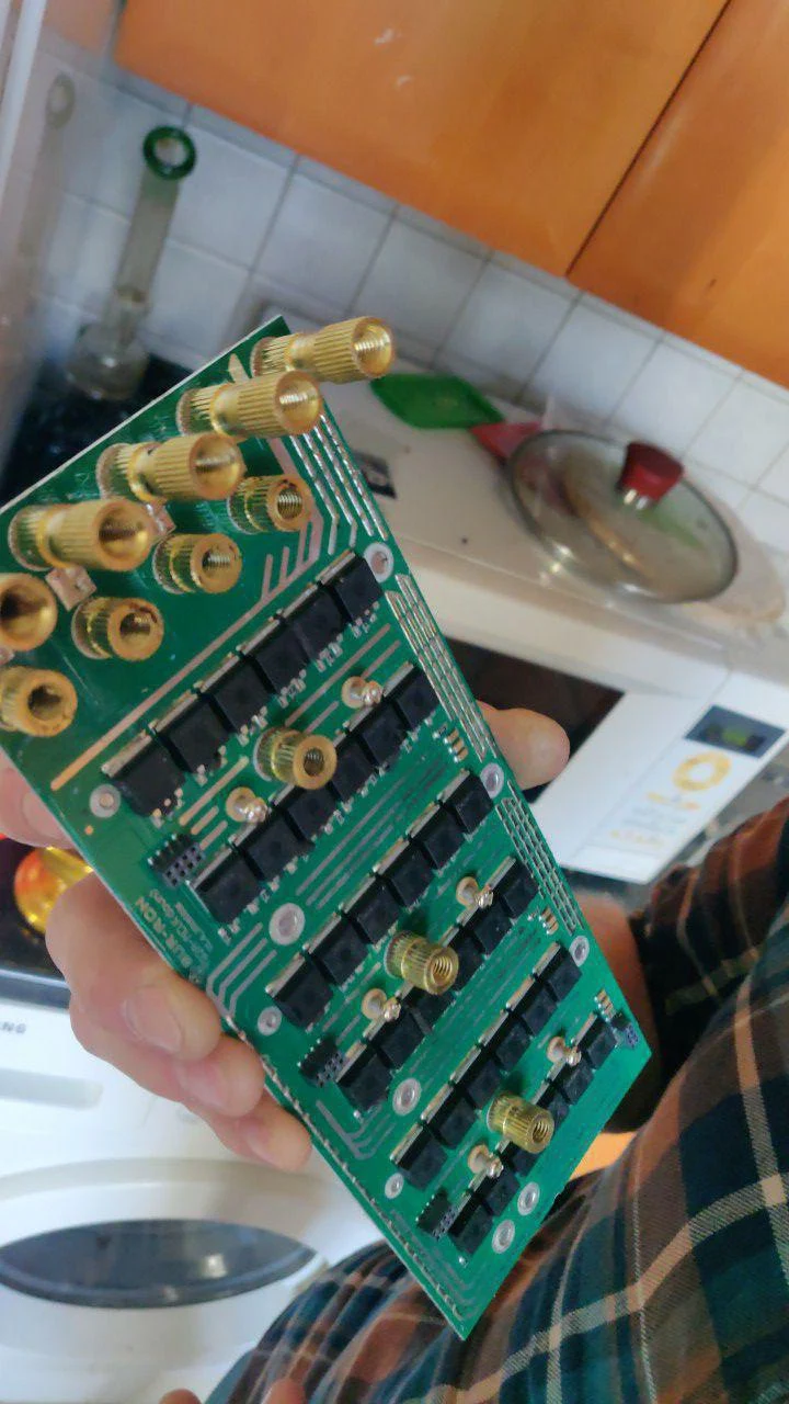
Can you share how you opened up the Sur Ron X case without damaging it? I've removed the 8 screws and gently to moderately tried to pry it apart but no movement.
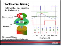
I don’t know which hall spacing they used but if it’s 60 degrees, there will be one position where all 3 will be on. Most motors are 120 degrees and you should not see all 3 on at the same time.
Do each of the sensor outputs toggle when you turn the motor? Each one should be on 50% of the time as it turns one revolution.
No idea where you can get a new magnet. Not many of these motors have burned up.
You can search for "8 pole encoder magnet". Here's one that looks close:
https://www.culinarydepotinc.com/parts-town-369822-magnet-8-pole/
I tested the Sensor it with a working motor from my friend.
Here are only 2 two sensors are on at the same time. Thats ok.
On my Motor, the entire sensor is working. All 3 positions are going on and off while turning. But on one position all 3 sensors are on.
In the picture can you see the Sequence which should be.
I ask me, what the hell can damage the magnet. There where only a few scratches from the sensor on the surface.
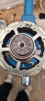
I already could pulled out the magnet now. I used a claw puller under the ball bearing to take off the bearing with the magnet.
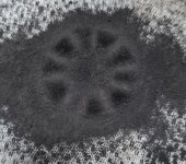
To test the amount of poles, i have painted some iron powder on the magnet with a cloth between.
Here you kann see, that must bee a 10 pole magnet. But one pole is weak.
With the term multipole magnet i could find some magnets, but not in the right size.
Do you think such a magnet can be created by DIY. ?
Turning an aluminum ring and insert small bar magnets was my idea.
Here are only 2 two sensors are on at the same time. Thats ok.
On my Motor, the entire sensor is working. All 3 positions are going on and off while turning. But on one position all 3 sensors are on.
In the picture can you see the Sequence which should be.
I ask me, what the hell can damage the magnet. There where only a few scratches from the sensor on the surface.
I already could pulled out the magnet now. I used a claw puller under the ball bearing to take off the bearing with the magnet.
To test the amount of poles, i have painted some iron powder on the magnet with a cloth between.
Here you kann see, that must bee a 10 pole magnet. But one pole is weak.
With the term multipole magnet i could find some magnets, but not in the right size.
Do you think such a magnet can be created by DIY. ?
Turning an aluminum ring and insert small bar magnets was my idea.
Attachments
Sure enough, your magnet is messed up. And it has 10 poles.
It would be possible to make one from aluminum or plastic with some tiny cylinder magnets inserted into holes. You'd need to space the holes very precisely and make sure the magnets were inserted to exactly the same depth.
Hard to say why it failed. Possibly it was rubbing against something and heated up enough to demagnetize that spot.
It would also be possible in theory to re-magnetize the spot, but that might be hard to get precise enough.
fechter said:Sure enough, your magnet is messed up. And it has 10 poles.
It would be possible to make one from aluminum or plastic with some tiny cylinder magnets inserted into holes. You'd need to space the holes very precisely and make sure the magnets were inserted to exactly the same depth.
Here's someone who did something like that:
https://ukmars.org/2020/09/improving-the-pololu-magnetic-encoder-more-magnets/
Hard to say why it failed. Possibly it was rubbing against something and heated up enough to demagnetize that spot.
It would also be possible in theory to re-magnetize the spot, but that might be hard to get precise enough.
@Fechter, thanks for your Help.
I have a CNC Mill and already created the 3d model. I am very curios if it will work afterwards.
I will try a to use a Alu ring with tiny 2mm magnets. Since the sensor needs the plus and minus pole for opening and closing, I have to place them in alternately.
I have a CNC Mill and already created the 3d model. I am very curios if it will work afterwards.
I will try a to use a Alu ring with tiny 2mm magnets. Since the sensor needs the plus and minus pole for opening and closing, I have to place them in alternately.
Attachments
I think the ring should be non-magnetic, but it wouldn't hurt to have a steel back plate on the side away from the sensors. Just the bearing it sits against might be good enough.
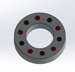
I have made my magnet sensor ring now.
Was a hard work to keep the magnets in there holes before the glue did his job. They always are flipped out to the nearby magnets. The sequenz is ok now, the motor is running. But after i take in the motor and want to drive, the motor does only jerking.
I can see in the Nucular Hall Table that the Offset of the sensors not near equal. Some are drifting up or down about 10 degree.
The positions of the magnets are fine. I have made it with my precission CNC machine.
Maybe the magnets are to tiny. The original ring had only small gaps between the magnets.
Attachments
You might try a very thin steel washer over the magnets to even out the flux. The hall sensors switch at the spot between the magnets where the flux is zero. If the magnets were big enough to touch each other, the transition spot would be more precise.
I have tried another version. And it works now.
It's made from POM and i used the magnets from a Pin Board. They are quite soft so that you can cut it with a knife.
I hope the magnet will not slip off again. POM is not the best material to fix it on steel. I used super glue to fix it.
In the meantime i going to create another base ring from phenolic fabric. Its more heat resistant then POM and better fixable.
Then i noticed that the shaft is getting quite hot and i think metal like aluminium will transfere the heat to much in to the magnets. I also want to omit the wall parts between the magnets to get a better transission in this version.
Attachments
Similar threads
- Replies
- 3
- Views
- 1,016
- Replies
- 15
- Views
- 5,196
- Replies
- 2
- Views
- 714
- Replies
- 27
- Views
- 4,169