Felixaustria
1 mW
- Joined
- Apr 30, 2016
- Messages
- 12
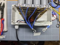
To pick up the current at the positive and negative terminals, it is not uncommon to damage a cleanly spot-welded battery by soldering on fat current collectors at the end. I suggest the following method: I leave the nickel strips protruding at the end and solder a 0.5mm2 or 0.75mm2 stranded copper wire to each end. I crimp these strands into a suitable ring cable lug. This ring cable lug can then be connected to the BMS and the power output using a screw connection.
Advantages:
1. No significant heat input into the cell to be expected.
2. Absolutely symmetrical distribution of the current if the strands are cut to exactly the same length.
Thermal tolerance: The pure nickel strips from NKON have a conductor cross-section of 8*15mm=1.2mm2 in the version for 21700 spacers and are (per cell in parallel connection) for 5.4A (optimum) to 8.1A (acceptable).
If you have 4 cells in parallel, this is sufficient for 21.6A to 32.4A.
If you have 6 cells in parallel, for 32.4A to 48.6A peak current.
Conclusion: I think this should be completely sufficient for all e-bike applications approved for road use and is technically far superior to the common practice of frying fat strands on the terminals.


