Tab cooling prismatics.

Ianhill said:
Don't try and limit others by your own ability i was fair to you but you keep been condescending of my ability and knowledge so watch on as i put a test rig together and start getting some useful data from cool cells not your hot air.

as i said, making a setup like that that works on a workbench is 100% not a problem. i have already done so and tried it. making one that can survive the shocks and viberations of a go cart for the packs lifespan is something else entirely.

and yes, i am condecending because you need to check yourself before you end up sitting on a gokart at 50mph enveloped in a massive battery fire because the tabs internally ripped and shorted because you didnt mitigate (micro) viberations properly.

there is a REALLY good list of reasons why no commercial application uses tabbed cooling.

understand, this topic is a nice academic exersise in battery cooling/heating. but actually hacking something together that has a pretty good chance to end up with you going down a track in a ball of lithium fire because a tab internally ripped is something you need to be aware of before going up this hill. we got PLENTY of examples on this forum from people with burnt down bikes, sheds, garages, homes and vechicles.
 
https://www.mdpi.com/2032-6653/9/2/22/pdf

Bit of academic source material.

This is not taken lightly the concerns raised are on my mind too and if the design dont meet criteria ill cut the plug i will not make anything wildly dangerous all points taken on board.

My idea is to use a prismatic cell with tabs either side like the lg 60ah nmc cell ive been contemplating the design layout but for cell safety they will be stacked as a pyle on the horizontal plane to keep tabs next to each other at 3.7v if i stacked in groups of 3 i would have the potential for 18.5v to flow between terminals in the event of a shorting incident so thats a no go si the packs CELL dimensions will be in the order of 100×300×300mm give or take as i dont have the items to hand measurements will be finalized.

There will be 20cells not 21 this way i keep the power leads on the same side of the pack for ease of wiring the 10 tabs either side will have a pcb that connects to the tabs and flows its heat to a small square below one tab then above the next and so on so theres space for the SMALL water block.

On each of these tabs i will place a small ram heatsink on a thermal pad so in total i will have 20 small ram heatsinks each one connects to 2 tab faces all be it the postive and negative that will be a single tab respectively then i will form a cooling loop and epoxy the tab area of the chamber shut once tested.

This is no rush game im brainstorming and hoping i can get a design together that i can then try and finalize and make it, this will be nothing but profesional and treated with the respect it deserves i got a holiday coming up and then i will get the kart in 2 weeks so theres lots of times yet to play this idea out.
Ive choose a sodi kart rs3 nice stiff chassis perfect for a first attempt i got the controller motor and active bms so give me time and this will get a good shot at success as any will give it and if it fails it wont be for the lack of trying with proper research i will not allow the 7 p's be a factor.
 
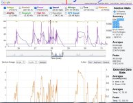
I just pulled 23.8 horsepower out of some Chevy 25Ah cells. They did not blink. The motor was blazin and the controller was a lil hot. 17,800w plus. 90 lb bike give or take.

The pack was built with a fan in mind. 12v, 120mm, PWM outputs on a Nuclear in mind. I do not think I need it. The pack did not get one degree hotter. On any of the sensors on the system, and with the thermal data. This shows a 9.72C peak. CA3.14 shows 28-40mOh for the pack IR. Data I have read states that the cells will not show any increase over RT until continuous current draw of 4C... 100A. From the limited data I got.

QS205. I did take pictures of it. I'll update when I can. The pack gets hotter on charge, than at this level of discharge. Hmmmm.

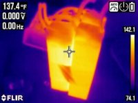
For reference, here is a pic of a RC lipo.. so called "65C " contin.. and only managed to push about 30C peak. This bike only pulled 163A on the 72v, 5Ah, 2mOh/cell lipo. Hot Potato Lipos are..... hot. Direct product of an undersized pack, faltering.

It is a little bit of a surprising volume for a Chevy cell NMC-LMO pack. It still gives good range and incredible power for its small capacity ( 1.85kWh) on this bike ( that can fit 3-4kWh of 18650 in it).

Point is.. I dont think we need cooling so much anymore... the cells are getting better and better.

Ianhill said:
Id thinking of using 21 lg 60ah li nmc cells that can deliever 240amp a cell but heating occurs nothing drastic but 20 mins of that build up would lead to a hot pack.

If the cells do not get hot, they do not get hot. Kinda what I am learning.

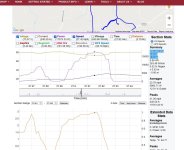
Can confirm they will zap 240A pretty easy. This log is made on a Kelly of 8kW rating. 72v system. KEB72801X. 240A peak up a hill @ 50mph.


flippy said:
also, adding more capacity and cells in this manner will give you a considerable less amount of voltage sag, heat production and capacity.


Yes kinda what I learned. I wonder about the threshold.. where is to small, and what is too hot.. I guess it is kinda self explanatory.. Either your cells can hack it.. or they cannot. Temperature yields the data of the application ( sized capacity)...

Still..... How do you ABSOLUTELY know if the cells will hack it or not? That is in the questions?


As for ones implementation and design skill, use of tooling and time, I will not say anything, for I have a disagreement there, Flippy. Regarding the merits of a 600 cell spot welded pack vs a 21 cell larger format pouch cell design, housing and whatnot included. Personally. Personally I have seen many spot welded packs fail for poor mechanical designs. Time is the essence of control and the amateur builder is not skimping on time where the investment of 600 cells is involved or else risk expense.

Some of us are faster than others. Some may build faster, some may build slower. Truth be told, not a level playing field. Not a good comparison. But Yeah.
 

Attachments

  • 212189309_4569592243071069_7820328052659981078_n.jpg
    212189309_4569592243071069_7820328052659981078_n.jpg
    109.3 KB · Views: 349
  • Th.jpg
    Th.jpg
    111.3 KB · Views: 349
  • HOTLIPO.jpg
    HOTLIPO.jpg
    13.2 KB · Views: 349
Ianhill said:
Exactly what it says on the tin tab cooling prismatics.

Whats the best method for simplicity but effectiveness....

I want to do this for a gokart idea i got the cells will be on the limit so need help or ill be lucky to get 150 cycles out if them but im going to design this clever so its not a big weight block on the side its going to be flat and in the floor pan 700×300×40mm in cell dimesion for a 21s 60ah pack then i got to apply a box and cooling

I'm a former karter, so I can't help but be interested in your build. I wish I'd have kept my old karts for conversion purposes now that battery tech has advanced to the point where I could have some real fun and competitive races. oh well, fewer broken ribs is okay too.

Ignoring any discussion of whether cooling is necessary, passive tab/battery cooling would be relatively easy to accomplish.

If I were to build a kart battery I'd go with a high AH prismatic cell with opposing positive & negative tabs on the ends for two sided cooling.

1_1__1_57.jpg


I'd use compression clamps made of aluminum bar stock for ease of assembly and attachment of the bms leads. I'd use fiberglass end plates with slots just to make assembly easier and safer, and I'd use docbass' method of making a copper positive and negative terminals for the ends.

file.php


Spinning magnets thread index of connection methods has all this of course...

https://www.endless-sphere.com/forums/viewtopic.php?t=111704#p1654866

I'd add FG side compression panels with threaded rods to compress the pack. The rods would extend past the panels each side to act as stand offs from the aluminum shell. Then I'd mount my bms on the outside on one of the panels.

I'd mount a couple temperature sensors to the pack ends and to the middle of the sides... I'd run a cable out to connect to detachable arduino nano to empirically test the worth of battery cooling.

I'd use both kapton tape then shrink tube around the clamp end connections for belt and suspenders approach to the electric insulation.

Then I'd make an aluminum enclosure/shell ~3/4" larger than my pack on all sides. I'd mount connectors to the shell, or route wires out via grommets. I'd place my pack in the shell centering it in the space. I'd cut teflon blocks the length of the ends about 3/8" thick each. These are to insert at the ends of the pack temporarily during the addition of the potting material so that once cured the teflon blocks are removed to create a void at the ends of the pack. The idea is to end up with the pack potted in transparent silicone potting gel about 3/8" thick on the sides and 1/8" thick on the ends. This material has decent thermal transfer, and absorbs shocks as well as being "re-enterable" meaning that you can carefully separate a pack retaining most of the gel to replace a bad cell if required.

Then I'd fill the end void with a special thermally conductive gel. Then on the outside of the shell I'd have mounted a length of aluminum heat sink with 1" deep fins on each end. I'd mount this in front of my seat where I used to have the gas tank. The idea is to have the ends act as large radiators.

I'd build a similar pack without the passive cooling and add the same sensors and run comparative tests to test the merit of such a system.

Silicone potting gel can rupture and release gasses if a pouch fails without creating explosion. The shell can be made leaky enough for the same purpose and yet be totally sealed to dust moisture etc due to the use of silicone gel.
 
I do not think I have posted a picture of this battery here yet.

Here: You can see the fan mount, compression case, compression straps, balance maintenance port,ect., and this pack pushed 18kW peak battery horsepower on a QS205 with a 8kW controller ... 350A phase. Turns out, I do not think it needs the fan for this (250A) load.

4 gage wire, 600A BMS. I am building a 50Ah right now for a(n) 800A controller.FANBOX.jpg


This is the log of the (5Ah, 72v) bike with the HK "65C" lipos.. Vs.... the Chevrolet cell ( 25Ah, 72v) in the same bike. Same bike, same rider, same same same. Big difference that the 5x capacity and higher quality cell offers. Chevy battery did 2x the power easily and 12 mph faster..... The Chevy battery measured 28mOh at best, the HK lipo measured 60+ mOh ( with its poor design, 10g leads, and EC5 connectors throughout). Both runs use average 70wH/mile. Where the HK lipo tried, and failed, the Chevy lipo kept on going.

The Chevrolet cell battery, is much lower IR, than the HK Lipo battery ( that just heated up to compliance).

lipovsEVcell.jpg
 
When I first heard about tab-cooling, I was very skeptical. I assumed the most cost-effective way to add some cooling to flat pouch cells was to insert aluminum plates between each cell.

However, the cells themselves are layers of thin aluminum and copper sheets. That should make them very thermally conductive, but the problem is the plastic sheets of insulation. These sheets slow the heat transfer from the centers of the cells to the broad/flat sides, but heat is unrestricted and free to travel from the centers to the tabs.

Years ago it might have been just an interesting question to test, but now its been tested. Tab cooling works better than skin cooling on flat pouch cells. I don't know how much of a difference there is, and I am curious for any ES member to perform some experiments and post the data.

In the pic below, I'm talking abut the "separator"

Pouch-Cell.png
 
I think the argument for submersion cooling of the battery with flow of immersion fluid over the tabs/bus bar should be considered. Dow fluid in a few useful temperature ranges is available.

The advantages to longevity and high discharge/charge applications is obvious. The fluid could also act as a vibration dampner in some of the applications discussed here.
 
Back
Top