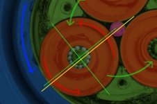
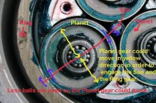
Thanks, I see now. It's hard to see in the pics, but the rollers are offset slightly. This works similar to the roller clutch on a Currie drive.
After some miles, it may be necessary to clean and re-grease the rollers.
Heat buildup could be a problem. Forced-air cooling would be a bit tricky to set up on a hub motor.
After some miles, it may be necessary to clean and re-grease the rollers.
Heat buildup could be a problem. Forced-air cooling would be a bit tricky to set up on a hub motor.
")