The SB Cruiser : Amberwolf's 2WD Heavy Cargo Trike & Dog Carrier

So far the tire/tube has been fine. The new tubes arrived today, but I won't be able to do anythign with them until Wed at the earliest (unless a flat forces me to).

But, life being what it is, something else had to break. Two things actually, though one was expected and I'd wondered how it lasted as long as it did. ;)

The first was the zipties holding the headlight toggle switch to the frame; both snapped as I turned it on the other night. Easy to fix.

The second was that a weld on the seat back snapped as I pushed myself back into the seat to start riding to work the next day. It isn't a critical thing, but it's uncomfortable because there's no back support (and I really need that these days).

I'll make a temporary fix by drilling and bolting it on, and then reweld it someday when I have the time (and energy, at the same time) to take the back off the seat and take the cloth off of it, so the welding doesn't damage the cloth of the seat itself.


If I"m lucky, I'm going to have over a week and a half off in the middle of August (broken with one day of work after 9 days off, then two more off). Depends on how stuff goes at work. It'll still be hot, and humid, but hopefully this will allow me to redo the controller / motor / etc wiring, and get the new Grinfineons installed in place of the generics presently on there.

Maybe be able to fine tune the CA3.14 setup stuff to get rid of the wierd and dangerous behavior it presently has. (which is what prevents me from using it to control *both* motors; I have to leave the leftside as straight throttle-only control, to ensure I still have motor power even when the CA3 is doing one of it's wierd dangerous things. )
 

Attachments

  • dsc08357.jpg
    dsc08357.jpg
    34.9 KB · Views: 3,683
  • dsc08355.jpg
    dsc08355.jpg
    31.9 KB · Views: 3,683
  • dsc08358.jpg
    dsc08358.jpg
    36.8 KB · Views: 3,683
  • dsc08359.jpg
    dsc08359.jpg
    29.7 KB · Views: 3,683
  • dsc07821.jpg
    dsc07821.jpg
    65 KB · Views: 3,683
  • dsc07050.jpg
    dsc07050.jpg
    57.6 KB · Views: 3,683
  • dsc07293.jpg
    dsc07293.jpg
    46.9 KB · Views: 3,683
The above repair, as well as the frame repair of the keel, are holding fine AFAICT.

Hauled more than 350lbs of groceries today. (deep sale on gatorade, got as much as I could fit in the cargo pod, plus two coolers strapped on the top deck full of other stuff).

Kept it under 15MPH with that load for the roads with traffic, and 10mph or less everywhere else, so if anything *did* go wrong, it wouldn't be quite as bad as at 20MPH.

The front disc brake (Avid BB7 200mm) worked perfectly fine even with this load. If I had enough traction in front, it'd probably be able to either slam me to a stop or snap the fork. :lol: But there's not enough for that, so it skids the wheel beyond a certain point.

If I had them on the rear, it'd be interesting to see how quick I could stop, without breaking anything. Someday I'll get around to making it possible to put rotors on the rear, and some caliper mounts, and get a pair of these for back there.
 
I'll have all of next week off, and the first couple days of the next, with the intent of doing some of the many major changes and fixes to the trike, primarily (and using up my PTO so I don't lose it).

So I took a trip to Harbor Fright today to get some of the tools and supplies like grinding discs, extra welding wire just in case, crappy nut and bolt kits so I don't waste a bunch of time looking for a matching nut and bolt, SAE and Metric tap & die kits, etc.

Would prefer better quality stuff, but with coupons in their mailers the cost is enough less I can almost afford HF stuff, while the better stuff is out of reach (well, I could get one of those for the price of three or four HF things, and it's fairly likely the HF stuff will do most of the jobs I need them to...when they don't, I'll worry about that then. )

Anyhow...some of the priorities (in order I remembered them, and sort of actual priority) are:

-- take the rim, spokes, and hub from a couple other old wheels and build a new disc front wheel to replace the bent up one.

-- tighten up the headset; I still havent' quite got the top and bottom clamps close enough together to eliminate all the wiggle. tried cargo straps but it didn't pull hard enough I guess. Have to try the adjustable long clamps I used to build the wooden parts of the trike.

-- paint the fork, add a fender (gonna be a fair bit of rain, probably, next month or so, i may have to ride in), add marker/signal LED strips to the fork legs.

-- fix up the canopy; needs some reinforcement at the corners in front where sun and overhanging tree limbs on some roads have damaged the vinyl material. Probably bend and rivet some thin tin or aluminum into hand-sized corner covers. Also want to remove the crossbar at teh bottom rear of the canopy, since I've always had problems on really bumpy sections of road (frequent) that bang my head on it a little. But have to first make a clamp or bolt setup for the end bits so they will stay in place and not rotate or bend without this crossbar; the structure is presently dependent on it's presence for stiffness. Redo the front LED strip, maybe add some side markers.

--Wire up the side markers on the body that I installed months ago but never got further with, including making the little transistor or relay circuits that will let them be always on as markers, except when turn signal on that side is active, when they'll blink off when the turn signal elsewhere blinks on.


-- building the handlebar "dashboard" switchbox for all the lights and traction system controls, and to enclose the CA within, etc. I've been locating pieces needed in my stuff, mostly switches and wires. Haven't drawn up the schematics for the electronics I'd like to add, so some of the stuff wont' be wired up yet, but at least want to get it built and installed, with the basics wired up for switching throttles/PAS/etc around or off, main light switches, etc.

-- switching over the controllers to the Grinfineons, which includes a new traction wiring harness from front to rear (probably leaving lighting alone for now), and hopefully recabling the motors themselves with the new Grin cable. Will probably leave the old wiring and controllers in place just in case something goes wrong with the Grinfineon setup that I don't have time to fix before going back to work.

-- after reopening/recabling the Stromer/Ultramotor, build it into a wheel with the Grin spokes and the old rim from the X5304 wheel, and replace the MXUS 4503 on the right side with it. If I can't reopen it (couldn't last time I tried) I'll just splice in as close to the axle as I can get.

--figuring out what the hell is going on with the CAv3 and PAS. (and wishing they'd fix the bug(s) in there about part of that for the high-range mode so I can go back to that and have usable amp/watt data). I've been trying to figure out how to write up what's happening, but there's so many little things that happen it takes pages. :/


-- If there's enough time, probably 3-4 days, I would really like to take the deck off to access and cut apart the frame there, rebuilding it from an H frame to an X frame. And going over it all looking for any cracks or defects.

-- Along with that, altering the outboard wheel area frame so it unbolts or hinges out and lets me pull the wheel out sideways instead of having to jack up the trike to almost tip-over-angle to get the wheel out from underneath. (not practical, sometiems not possible, roadside anymore, with my SI joint problem). While at it, rebuild the inboard dropouts so they aren't dropouts, but rather a shaped hole for the inboard axle to slide straight into. Then the side plate with the other one slides straight onto the axle there. Should be much stiffer and less able to twist the axles vs each other under high torque loads, which I think is what contributed to breaking them before (plus crappy materials/workmanship from the manufacturers).

-- Make disc caliper mounts for the outboard sides, too, and get two more Avid BB7's for the rear wheels. The deal for the 200mm rotor and caliper is gone now, they only have 180 and 160, for the same price, so I'd probably just get a different seller's caliper-only deal for $15-20 less, and use the two 180mm rotors I already have, ordered long ago from http://ebikes. ca Grin Tech to try out on the crappy YUS calipers I had at the time (which suck and are completely useless, even with teh 160mmrotors that came with them).

The new Grinfineons will give me proportional regen so I can brake with precision rather than on/off and help keep from damaging axles/dropouts, but having mechanicals will still be necessary in some situations, like when I have heavy cargo on the trike and the trailer too, or if I need to hold the wheels locked at zero speed. (parking on a slope, etc). I do have the handbrakes from a wheelchair for the latter, but they only push against the tires, so if they're not fully inflated, or not quite perfectly seated in the dropouts for some reason, they don't have as much holding power--and they can only be used when I'm stopped and can reach back to each wheelwell to pull the levers one at a time. The discs I'd have a handle on the bars for....

-- build battery boxes for the sides of the front triangle to hold the traction pack, to move it out of the cargo / seat box, to allow for more cargo in there (and shift some weight to the front wheel; almost all of it is on the rear wheels right now). This seems easy, but the cells are rectangular flat units about the size of a largish book and a quarter inch or so thick, so whatever I make has to stick out quite far to the sides, but can't go down or back very far, because my feet have to fit on the pedals going around there too. And with the new doulbecrown fork, there's a lot less room since the tubes between the clamps arc thru the same space I would have put battery in. May not be able to do it at all.

-- Add a post near the cranks for a front derailer so I can pedal along at higher speeds (10-15MPH) for what exercise I can handle before things just hurt too much. Can only keep the chain on the granny ring right now; the larger rings are inaccessible cuz it'll just fall back to the granny. That makes top pedal speed around 5-6MPH; past that I'm just spinning, which while it keeps my legs active they're not getting much actual exercise, and doesn't let me use the torque sensor as it's designed.


-- Would really like to totally redesign the axles to hollow thickwall large-diameter "pipes", but have to have new side covers with much larger bearings for that, and I don't yet have the ability to do that (or money to pay someone). Then use clamps around the entire diameter of the pipe axles to secure them, possibly keyways if necessary. Either way this isn't happening next week.


Side note:

The Grin 12-LED headlight is dying row by row. One outer row started flickering a few weeks ago, now it's dead and the other outer row is flickering. Once it dies the inner ones will probably be next. :/ Since it's potted itll be too much of a PITA to fix, so I'll probably just add white LED strips as a frame around the ex-KIA headlight or something, isntead of the Grin light next to it. (since the Grin light doesn't actually do much as a headlight, just a marker to show I'm there if I am not running the car headlight).


Also, I'm thinking about reinstalling the regular DOT taillights and turn signals on the rear end (only has LED strips right now), since the LED strips aren't as visible in daylight, or as instantly recognizable to drivers. I haven't had any particular problems because of that, but I have noticed some drivers don't react to the LED strips like they did to the DOT stuff, under bright daylight conditions at some times of day and directions I"m riding in vs teh sun angle. There's stuff I could do to make the LED strips more constrasting, and I could add a lot more strip area, and I'll probably do that eventually as antoher experiment. But I have so much else to do right now that just bolting on the old lighting unit and plugging it into the box under the trike is quick and easy (except I think I have to rewire the connector on it to match the new pinout I chose).
 
When moving the trike from where I parked it yesterday after the store and trailer trip (see the Mk III trailer thread) to the porch shade to work on it, I found the lighting doesn't work at all. Nothing wrong with the battery, so it's *probably* the switch, will have to look at that and wiring, and fix it. But it's an "easy" thing to fix, most likely, so not top priority.


So I started with this part, after getting the trike into the shade on the back porch and rolling it onto it's side (which almost took me out; had to rest a while after that with my SI joint complaining), and setting up a mister and fan to make it possible to stay out there and work all day:

-- switching over the controllers to the Grinfineons, which includes a new traction wiring harness from front to rear (probably leaving lighting alone for now), and hopefully recabling the motors themselves with the new Grin cable. Will probably leave the old wiring and controllers in place just in case something goes wrong with the Grinfineon setup that I don't have time to fix before going back to work.

But I went ahead and took out the old controllers and the wiring underneath, except for the shunts and main battery cables to teh shunts. Then I painted the whole underside white, to make it easier to see stuff under there when I can't actually roll the trike over on it's side.
dsc08366.jpg


I left all the stuff from the bars to just before the controllers, and connectorized the controller end of it to match the Grinfineons (I don't yet want to modify the controllers at all, just so I can see how they perform "factory fresh", and will only modify them as needed to get what I want out of them or to neaten up wiring if necessary (like make the phase and battery wires shorter, perhaps).

I fixed up some other bits of wriing that have been hacked at since I originally did them, replacing electrical taped twisty splices with proper ones heatshrinked up and soldered, with staggered splices, etc.

Added corrugated plastic split-tube covers for the major wiring bits, to protect them against scrapes and whatnot.


Got the Grinfineons hooked up and basic offground testing done, so they operate in sensorless / trapezoidal mode, each with it's own throttle, but common reverse and ebrake connections. Verified reverse works on both.

One problem I have to troubleshoot is that the nonstickered unit doesn't appear to respond to the ebrake lever with braking, it just stops powering the motorpower. The stickered unit does brake the wheel with the ebrake lever regen. They should both do that.
dsc08378.jpg
dsc08381.jpg


On the leftside motor, which was still 12g wiring up to the PP75s, I unsoldered the PP75s and replaced them with PP45s to match the Grinfineon. But on the rightside motor, which has 10g (or larger?) wiring, with the solid copper magnet wire going inside it, I didn't want to mess with that. So I made adapters from the 75 to the 45, just taking some old 45s with 12g wire already in them cut off a motor or controller some time back and in my junk box of anderson stuff, leaving an inch or so of wire, and soldering that wire into the cups of the 75s I took off the other side. Then just put them betwen the Grinfineon's 45s and the motor's 75s. Not ideal, but quick and easy without rewiring.
dsc08379.jpg
dsc08380.jpg


Complete rewiring of the motors will come later, since I have to add hall wires back in on the rigthside motor anyway, and have to fix two of the hall sensors (or their wires, they're stuck at 5v) on the leftside motor, to get the sensored / sinewave operation mode that I want out of these controllers.


Most likely before going back to work next week, I'm going to connectorize the more powerful of the generic controllers to match the Grinfineon setup, so I can carry it with me and just swap it in if something goes wrong with a Grinfineon.


I didn't get this completed:
-- If there's enough time, probably 3-4 days, I would really like to take the deck off to access and cut apart the frame there, rebuilding it from an H frame to an X frame. And going over it all looking for any cracks or defects.
but I did examine it closely for problems, and didn't see any, before painting it all white.

This is the mister/fan:
dsc08364.jpg
dsc08365.jpg
Mister is made from some old misting nozzle from a spray bottle, which was broken / cracked, so I reshaped the plastic so it would friction fit down into a hose attachment for a dripper tube system. Screwed that to the hose, hung it from the tree branch behind the fan, and used the fan to pull the cooled air and blow it onto me. Made something like a 10 degree difference in actual air temperature, plus cooling me off by the airflow, too, so was livable (won't say comfortable, since it started out over 105F and humid).


The original plastic (with a steel strip) iron holder on my soldering unit disintegrated, so I made a new one with a bit of gorilla glue holding the "button spring" out of an adjustable-length bit of retail signage tubing to the spring out of a dog tree-run tie-out.

dsc08376.jpg
dsc08377.jpg


Side note: The Grinfineons are not identical; I didn't notice until hooking them up on the trike, but one of them has a sticker label on it with handwritten numbers, and that one does not have any labelled heatshrink on the connectors, unlike the unstickered unit. The stickered unit also has it's CA connector covered over in a double layer of heatshrink, really thick stuff, so it can't be used unless that's removed. I'm not planning to use the CA connectors on the controllers, at least not ATM, so it doesn't matter just now, but it is very strange since both of these came from Grin in the same box, and should be from the same batch of controllers (the ones on clearance due to the misprogrammed LVC). Makes me wonder what else is different, perhaps inside. :? It almost looks like the stickered one skipped at least one whole step in the manufacturing or post-manufacturing process, or was being done by a new-hire, etc. Almost worries me...but not quite enough to open either one up yet.

dsc08367.jpg
dsc08368.jpg
dsc08369.jpg
dsc08370.jpg
dsc08371.jpg
dsc08372.jpg
dsc08373.jpg
dsc08374.jpg
dsc08375.jpg
 
You mentioned adding a fender. I do have a front one that I found on the side of the road. I'm pretty sure it is from one of those yellow rental bikes since it is yellow and fairly heavy duty. You have to fiddle with how to connect it since one side of the rather thick wire that connects the fender to the lower part of a front fork is broken off. But other than that it is a pretty robust front fender in good shape.
 
If it's 26" it'd fit the trike, and would go well with other parts like the headlight and SMV sign and ball hitch that were also roadside finds. ;)

THe wire "U" from my old fender is still intact, but the fender itself is crumpled and bent in a couple places from that crash that broke the fork. I'd been figuring on having to hammering that out enough to go back on (since this fork will give me more clearance than the other one), but an intact fender would be easier. :) Color doesn't matter cuz...paint. :lol:

I got up quite late today, had my alarm turned off and Yogi didn't wake me up for breakfast, which is unusual, since he was definitely hungry and usually wants me up when it gets light outside. Good thing I'm off for the whole week....


Now, out to start the lighting troubleshooting (at least it's well-lit out there right now, and only about 100F ATM, but heating up).
 
amberwolf said:
If it's 26" it'd fit the trike, and would go well with other parts like the headlight and SMV sign and ball hitch that were also roadside finds. ;)

THe wire "U" from my old fender is still intact, but the fender itself is crumpled and bent in a couple places from that crash that broke the fork. I'd been figuring on having to hammering that out enough to go back on (since this fork will give me more clearance than the other one), but an intact fender would be easier. :) Color doesn't matter cuz...paint. :lol:

This is the fender. I'll have to figure out when I can get it over to you.

fender_sm1.jpg
Fender_sm2.jpg
 
wturber said:
This is the fender. I'll have to figure out when I can get it over to you.
The bracket on it looks pretty much like the one on my bent up fender, except mine has a "loop" for a bolt to go thru it and secure it to the fender (bolt goes thru the fender). I'm sure I could make it work.

I suppose I could also bend a bit of steel "wire" into a loop and weld it to the end of the existing bracket.

I"m here all week, working on the trike and other things. I'll probably go out for test rides and such now and then, but you can reach me on the phone via text (or call, but I don't always hear it ring).
 
Been working on the lighting wiring today, first finding that the switch itself has gone bad; move it just right and it works but mostly doesn't make contact inside.

When I looked at how it's all wired in, I found I've done so many hacks and experiments and addons that it's a mess in there, so I need to redo a number of things. Enough of it that it's almost like starting from scratch.

So I did, for some of it. I added a "busbar" terminal strip for the things that will have quite a few wires going to them, like the main "12v" positive and ground, and the turn signals. I had two types, one for round lugs, and one for the push-on "spade" types. THe round lugs would be more compact, more secure, better contact, being held down by screws, but harder to just undo one thing for troubleshooting or repair. The push-on would be less compact but much easier to connect/disconnect.

So I went to find the lug kit I had around here, but it's nowhere to be found. No idea what I did with it. Ran across a box with a bunch of buttsplicers (red), but no kit, and no round (or fork) lugs. I found a little bag of a dozen or so pushons though, and I have a handful of wires in a box with those already installed, so that's what I used. I'm still going thru all the wiring but so far the main grounds and the main positives are connected to the terminal strip.


Since the handlebar control wiring is also in there, and some of it is mixed with it for grounds and such, I kinda had to redo taht stuff too, so it is taking many hours more than I expected or wanted, partly from dexterity problems, and partly from doggie interruptions, heat getting to me, etc.


I'm about 25% done with the wiring; the most time consuming part is to disconnect one connectoin point that was previously just soldered as a big ball / star point, and electrical taped, and to redo that as heatshrunk neat connections, while also making good notes of what connects where.

The latter is needed because its' too complex for me to remember it all anymore, so for instance right now I've already got a few orphan wires that I don't know where they go, so I have to figure that out wire by wire, tracing it out and continuity testing, so I can hook them back up where they're supposed to be.


I'm also replacing some of the wire itself, as I used whatever was at hand at the time, and would prefer safety and consistency, so I'm using new wire out of that roll I found at goodwill a while back, for some things that need pairs of isolated wires, and such.


Also, I had experimentally added, or done emergency repairs, to a number of things on the handlebars, and instead of using wires in the main bundle cable, I'd run separate wires for each thing, making the tiller tube look like something out of a Borg episode. So I'm also removing those, and using wires in the main bundle cable instead, to get the mess off there. (not only is it messy, it increases the chances something will catch on a wire and rip something loose, whenever I"m doing something with that area of the trike, or if the dogs are exploring it, or wahtever).


Some pics of the partly-neatened mess-in-progress.
 

Attachments

  • dsc08387.jpg
    dsc08387.jpg
    57.7 KB · Views: 3,549
  • dsc08386.jpg
    dsc08386.jpg
    53.3 KB · Views: 3,549
  • dsc08385.jpg
    dsc08385.jpg
    64.8 KB · Views: 3,549
Gonna have at least a couple posts with some info and some rambling and some troulbeshooting....


Still slogging thru the handlebar and "triangle box" wiring, for controls and lighting. They're *almost* done, just have to tidy up the main control harness ends where all the wires split out, and wait for a couple of things to arrive to wire the lighting the new way.

I've been running all the lighting current (except the car headlight) thru the small 24g wires in the bundle harness, which has a bunch of wire pairs. Turn signals and brake lights are using a complete pair per signal, so double the capacity of the single 24g wires, but it's still kind of a small wire for this, especially as I add more lights (even though they're LED strips), plus the trailer. The two main front bulbs are still incandescent, as is the one in the lefthand bar mirror. (hoping to change those, too, eventually).

So since I already had a pair of automotive 30-40A relays (from a Methods carepackage years back), I decided to use them to do the actual turn signal switching, down inside the triangle box, and just use the stuff on the bars to control the relays. Then I realized I could just move the turn signal blinker itself down there, eliminating the need for turn signal relays...but I could still use the relays to switch all the downlighting, the headlight(s), brake lights, etc., so the switches on the "console" can be small low-current units, and not run any heavy wiring on the bars (I think the small wiring will handle the two turn signals on the mirrors ok).

I can also make a relay do the job of turning on the 12v power automatically when I turn on the traction battery disconnect, by putting a big enough resistor in series with the coil to keep the current at 58v down to what it would be at 12v. I did this on the "reversing" relay I used to use on the old controllers (not needed now), and it worked fine. It does mean another small drain on the traction pack, but it should be a small enough current to not matter for a 40Ah pack. ;) This relay will go in the seatbox with the batteries and cutoff switch, unlike the rest that go in the front triangle. It will mean I don't need another switch on the bars for main lighting power.

I don't have quite enough relays to individually control all the lighting groups, but my brother helped me get a 6 pack of 30A relays that have built-in blade fuse holders, which seemed a good idea in the unlikley-but-possible event of a wiring problem or short. So the relays will not only handle the loads themselves, but they'll protect my control wiring (which is a PITA to fix) from potential damage.

(I have had to replace the harness TWICE in basically one (two) days, couple years back I think, because I was replacing some wires and making a new harness, and wiring some stuff up with power on cuz it was easier, then shorted something whihc melted and burned several wires together....making me have to start completely over again...if it had been fused, that probably wouldnt' have happened, and it definitely woudln't have happened if I had used relays to handle the current instead of the control wiring.... )


So, I've got all the lighting working in the original way, just waiting on the relay/fuse units to arive tomorrow to do that rewiring. but it should be simple, if not quick, because I've already neatened up the stuff and made a new diagram / list of what goes where. ;) (it's pretty badly drawn so I need to put it in the computer and make it readable, and print a copy to keep on the trike, and post one here). Was going to mark the actual wires with sticker tape notes but seem to have misplaced the stuff I could write on and leave there.

I've also been using the spade connectors and busbar to connect all the stuff that has several wires that go to one point, instead of direclty connecting them. This makes the harness a LOT neater and easier to figure out and troubleshoot, or modify, if I ever need to. Also prevents some troulbeshooting from being needed, because there's no stress between teh groups yanking on each other under vibration, pulling wires out. But I didnt' have enough connectors, so he also helped me get a box of assorted automotive crimp-on connectors, that should have neough of what I know I need, plus other stuff I may use for some other parts of the trike later (or other projects).

As much as I hate the problems connectors can cause, sometimes they solve a big enough problem that the risk is worth it. :)


Anyway, while it isn't road tested yet, the wiring is "complete" enough that I *could* ride somewhere now if I had to.
 
Now for some bad news:

The Grinfineons don't work identically, even though they should be identical, from the same batch. Also, both of them differ in actual operation from what they are marked as, for at least the throttle input range, possibly other things I haven't determined yet. So far just offground testing, with the trike on it's side still.


First, both of them have Throttle Range of 1.00v to 4.00v laser etched on the case. But they actually respond only between 1.36v to 3.65v, using my Fluke 77-III multimeter, with the Fluke leads, and a verified-good battery in it. A Centech meter reads essentially the same, within a few hundredths. Readings are done at the back of the Grinfineon throttle JST connector itself.

Additionally, if an input greater than about 3.9v is used on the throttle signal (output via the CA, when I set it to the specs laser-etched on the cases), the controller will spin the motor full speed for about a second, and then it will stop operating the motor, letting it coast down, for about 4 seconds, then it will cycle between these continously.


Next, the unstickered unit doesn't respond to an Ebrake lever input at it's connector (grounding the signal pin) by regen braking. It only turns off motor power. That's a problem; it *should* give half of maximum regen braking when that signal is grounded.

Also, if you have the throttle engaged, and then engage the ebrake, it stops driving the wheel (but doesnt' brake it), but then disengage the ebrake, it does not resume at the present throttle setting, the wheel just coasts to a stop.

Letting go of the throttle, and reengaging it, *sometimes* resumes operation. Sometimes it does not. Sometimes the ebrake signal must be "pumped", engaged and disengaged, to allow the throttle to resume operating.

This is not a problem with the lever, wiring or signals. The same ebrake signal is wired to both controllers, and it simultaneously works correctly in the stickered controller. I have also swapped which throttle operates which controller, using independent throttles, used the CA as intermediary in various throttle modes, and even swapped which motor is being operated. The problem exists the same, in the unstickered controller only, regardless.

I am going to make a Y-adapter so that a single throttle can be used to operate both controllers, meaning I can also use the CA to have PAS operate them both. (but I can also just disconnect the adapter and get independent throttles back). Eventually I'll do this at the handlebars (perhaps with a relay to switch modes down at the controllers themselves), but for testing this is good enough. It will only have the signal and ground wires in it, no 5v connection, so the controllers' 5v will remain independent as they are now.


The stickered unit's ebrake signal does do regen, but oddly if you are at full throttle, while it reacts pretty instantly to start braking, it takes at least a half a second to *release* after the signal stops, and begin operating the motor again at the throttle level you're at. If you are at a low level of throttle, it appears to be instant release. I suspect it is actually ramping back up internally, at a fixed rate, so a lower throttle level takes less time to re-reach than a higher one. I don't think this will ever be an issue in practice, as I don't typically hold the throttle in position while braking.


I still have to test these on-ground, but if the ebrake problem persists under load, that controller will need to go back to Grin for repair or whatever, since they can't be reprogrammed by the user (and it's probably a setting).

I also have to get the halls in the motor wired out and working, so I can test them in sensored / sinewave mode, and make sure those functions work correctly.
 
Some problems with CA 3.14 (release) operation, independent of the controllers. Still only offground testing. ONground might be different.

I think it's a bug, but not sure; I could be misunderstanding what's happening:

If I have the throttle in Speed, Current, or Power mode, and i hold it at say, half throttle position, the CA will still ramp up to full throttle output; it's fairly rapid but not instant. If I hold it at a low position, it may take a couple of minutes, but it will still reach full throttle. The timing is different for different modes, but it still happens.

I understand Speed mode doing this, because the CA thinks I'm sitting still (the speedo is not on the motor wheels), and it's trying to make me reach the speed I've told it to by throttle.

But in Current and Power modes, it *can* read the shunt, and there *is* current draw, power usage, so it should at a low enough throttle draw enough current/power to be proportional to that. Maybe it's just not enough, off ground. I'll have to try it onground and see if these behave as expected there.


I *think* it *should* just hold the level I set it at. (proportional to the range I set it up for). But it doesnt'---it *always* ramps up to full, eventually. You can watch this happen on the Diagnostics screen to the "left" of the main screen--the input throttle level will remain steady, yet the output ramps from minimum to maximum, only varying in the time it takes based on the input level.

If I set the mode to PassThru, it operates as it should, and tracks the input, though it does scale it proportionally to the voltage limits it's set up for.

It also works mostly as it should in Bypass, but the CA3 page says:
Bypass: This mode is the equivalent of connecting the throttle directly to the controller to completely eliminate the CA from motor/controller behavior. This differs from PassThru mode in that ThrIN is sent directly to ThrOUT with no processing whatsoever: no min/max range adjustments, no ramping, no limiting, and no autocruise or PAS support.
yet it *does* process it, according to the monitor screen. It proportionally scales the input just as if it was on PassThru, etc. I haven't tested PAS or anything else with it in this mode to see if the rest of it works like it should per the description.


Another (minor) problem is that even if you set it to 99.99v/second for any of the "ramping" it still takes visible time for the voltage to reach max from min, if you "slam on" the throttle. If you set it to 00.00 it takes far more time, but it isnt' actually ramping as fast as the setting implies.


A more major problem I haven't been able to tune out, is that the TorquePAS (TDCM BB) stays engaged at full output for at least 3 seconds after the cranks stop, even if I take my feet off, or even if it's offground and I just move it by hand.

A worse problem is that sometimes it retriggers the output, for instance after I've stopped at the gate at home, and I take my feet off the cranks. Even if I am extremely careful not to push on them, and they don't push forward any detectable amount, suddenly the motor begins to run again, trying ot push forward at full power. Thankfully the old generic controller's sensorless operation wasn't very good from a stop, and the trike is heavy, so it couldn't just slam me forward into the gate (or the dogs if it happened once inside the gate). Or any of the other zillion situations in which this can (but does not always) happen.

I had *thought* that the PAS modes required a certain amount of rotation before the CA could output any throttle signal; this is how it operates when I am riding, and when starting up normally. But sometimes, like in the above case, it doesnt--and it only seems to happen when I'm stopped, but that may just be that I haven't noticed it any other time.

The torque sensor is zeroed, and I've rezeroed it and then tested over and over and caused it to happen even when it's zeroed, so there shouldn't be any (or enough) torque causing the CA to react, and there is no cadence sensor output (because the cranks don't rotate). Unfortunately the only place you can see the torque sensor's output state is in Setup, and it doesn't operate the throttle with it while you're there, so I can't actually see what's happening at that moment, according to the CA.

Reversing crank direction immediately lets off output in both cases, but that's a problem if my feet aren't on the pedals anymore. I have to instead grab the brakes, and reach down to turn off the trike at the battery cutoff. WHen I switch it back on, even if I haven't touched the cranks, the system doesn't try to do anything "by itself". So...I dunno what's going on, if it's a CA thing or a TDCM BB thing (electrical/mechanical problem).


I'm too tired to process any more reading about the CA. Been dredging up threads about it, and reading the UUG, and teh CA3 page here
https://www.ebikes.ca/product-info/cycle-analyst-3.html
and it's just all mixed and blended into a colorful paste in my head right now. :/
 
I found this in the manual for the Grinfineons:
Normally a sensored motor/controller setup is somewhat vulnerable to damage of
the hall sensor itself, the hall wires, or the hall connector pins. If this happens, the
motor will run very rough or not at all. On the Sinewave Grinfineon controllers,
the control logic will still be able to operate in sensored sine wave mode even if
one of the hall sensors is damaged as it can interpolate the missing signal.
However, the initial starting can be a bit rough, and the ebrake input no longer
does regenerative braking but just does a controller cutoff.
That *is* the action the unstickered controller is performing, but it shouldn't be, because no halls are connected at all to either one.

I did hook them up on that controller with that side's motor at first, but since two of them didn't work (stayed at 5v) I disconnected them before doing any more testing. So the controller shoudln't be in fallback mode, it should be in pure sensorless mode, and allow regen braking via ebrake input at the 50% braking level.

I guess I'll have to get the sensors fixed in the motor and retest, to see if this "fixes" the problem, and resets it back to teh correct mode.

I did not try hooking up the stickered controller's halls, because that side (right) doesn't have any wires for them yet, and when I cross-tested teh cotnrollers with the opposite motors, I didn't hook up halls just phases. So I *could* test to see if this "wrong-mode sticky" happens with that one under the same conditions...but then I woudln't have regen in either one from the ebrake signal if I couldn't unstick the mode.


However:

It may not matter, because I can't even tell that regen braking is happening at all, on the one that does work, at any speed from 20MPH down to zero. AFAICT the coastdown time is close enough to the same to call it the same, with and without using the ebrake-connector regen braking. It definitely receives the signal, because it cuts motor power when I use the ebrake lever.

It's pretty sad, because with the generic crap controllers, the regen is strong enough to pull hard to the side that's being braked, and stop me pretty quickly. It's not tire-skidding or anything, but it's certainly useful.

The present Grinfineon braking level of 50% (on the one controller that will do it) is completely useless.

Oh...it might make a theft deterrent, because it does make it about twice as hard to pedal, but I can barely pedal anyway, so that's not really saying much. :(


I did test the y-cable to operate both controllers off the CA's throttle output, so that PAS can operate them both, but it's not that helpful until I can tune the PAS to operate smoothly. It's still basically on/off right now, with a speed limit via preset for 5, 10, and 20mph, so having the full power available to that is overkill.

It *is* useful to have it available for a single throttle, but I'm so used to having them separate it'll take a while to get used to it to use it "safely", especially since the throttle used on the CA is from Grin (the flat-tab either-left-or-rigth-side unit) and it has a very narrow usable mechanical range, so it's hard to control the power level.

Current or Power mode would help with that, but since the CA has the random super-slow rampup bug when in High Range mode, and for safety I have to use Low Range mode with the wrong shunt value entered, the current or power the CA reads is way too low compared to what's actually happening, and so the control is proportionally coarser. :/


Since the cruising current (10-20A) is well within a single shunt's 45A capability, and the peaks (of 70A or more with two 35A controllers) should only be a few seconds, except when hauling really heavy loads of a few hundred pounds, I'm considering cutting one of the two shunts out of the system (just cutting the ground wire on one side, so I can easily reconnect it if there's a problem), so I can use low-range normally with the 1.0mohm shunt value in the CA.

That will at least let me test the system in some "normal" way.

I could also just plug the CA directly into the PAS-operated) controller. It would only read the power used on that one, so it would be more accurate than if it reads them both and I'm operating the throttle on the other one. But I cannot use the PAS on both controllers this way, at least not and have the CA accurately measure power usage. I could fake it by doubling the shunt value entered in the CA, so it "measures" both controller's usage, snce they shoudl be about the same...but it won't be quite right.


I'd much rather just use one shunt for main battery usage, for everything that's attached to it.


The connectors and relays for the lights arrived so finishing that up is next, and adding some small switches on a small panel on the bars for them. (I just don't have the time and energy to build and wire the big dashboard panel in the next couple days, along with everything else I want to get done, so that will have to be a longer term project, to do a little at a time, until it's ready and then install it. All this other wiring stuff has just taken way longer than I intended it to--it should've been done the first day, but it's taken four already, and still one more to go!).

The lights themselves are basically wired up, or at least connectorized for the reiays, so there's not much wiring to do to add them (just the switches and connecting the control wires to each end, and the ligth wires to the relays and power).
 
14 hours working on the trike today, just "finished" (too wiped out to continue) and all I got done was:
-- adding the headlight relay and switch,
-- finishing the redo of the front turn signal wiring,
-- adding the "new" rear DOT turn signals (with LED bulbs),
-- painting the fork (white primer, red final tomorrow after primer has dried)
-- fixing a broken wire on the rightside downlighting of the side of the cargo pod

Wanted to get the switches for individual lights (like the canopy) wired in...maybe eventually.

Tomorrow...gotta:

-- build the new front disc wheel (the old one is just too bent up to use, from when the trike broke in half; maybe I can just move this hub/spokes over to a different rim. If I can't finish it and have to ride, I have a 24" wheel "identical" to the bent one'; it'll change the ride and geometry, but that might be an interesting experiment to try anyway.

-- take the hubmotors off and add hall wires (and fix any broken sensors)

-- cut the wire to one of the paralleled shunts and set the CA back to the 1.0mohm so Current or Power mode throttles will actually work.

That will probably take all day...but if it doesn't, I'd like to:

-- add the tube to the frame behind the cranks to put a derailer on to be able to pedal "usefully" along with the motors at medium speeds.

-- Reline the cargo/seatbox with new insulation (the old is crumbled up), and insulate the inside of the rear cargo area too.

Then I'll still have two more days off, will see what else I can get done. The wishlist is really long....
 
Yeah, they have trike versions too (so does UPS). There's a few threads here and there about them. I think UPS uses the Cycletruck brand. DHL has at least two or three versions I've seen posted, plus the one you show there.

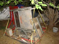
SB Cruiser doesnt' direclty ahve that much volume in it's cargo area, but it does on the Mk IV trailer. At one time I was going to make the Mk V trailer big enough to carry a standard pallet (at least 4'x4' cargo deck), but I think that would be too wide. However, it's supposed to be able to carry all four St Bernards, so it might have to be that wide, and probably at least six feet long (not counting the hitch/etc end), to carry them inside the insulated "horse trailer" type 'box", along with the air conditioner (might just be an evap) and battery for that.


I didnt' get the hubmotor halls redone. Just not enough time, everything else is taking way longer htan planned.

I did get the:

-- front wheel rebuilt

-- fork painted

-- front LED strip turn signals installed on the fork

-- downtube LED strip reinstalled and wired up

-- replaced the dead and missing sections of the front canopy white LED strip

-- replaced the dead sections of the rear canopy red brake/tail LED strip

-- moved the wiring for the forward canopy stuff (front edge strip, canopy downlights), which used to be ziptied along the "rack tube" (but the zipties quickly rot and break, leaving it dangling), to inside the tube till it gets to teh top of the cargo area deck, then it runs inside like before.

-- separate wiring and switch for the canopy and cargo deck lights (so I don't have to run all the lights just to use the deck lights to work on stuff with the deck as a table, or use the canopy lights to see stuff on teh handlebars or in the cargo/seatbox). Wanted to add lights *in* the box, but didn't get that far.

-- mounted a speed sensor and magnet for each of the hubmotor wheels (the main sensor is on the front unpowered wheel) but I havent' run the wires from them to the handlebars yet. When I do, I'll put an ON-ON-ON switch in the switch cluster to have the CA monitor either front, left, or right speed sensors. Of course, when monitoring the rear wheels I'll have to change the wheel diameter in the CA.

-- cut the ground wire of one of the two shunts and set the CA to 1.000mohm to match it so I could try current / power throttle modes on the CA

-- experimented with Cycle Analyst settings to see if I could tune the PAS to be useful as more than on/off and get the throttle to be usable with current or power modes, rather than speed or pass thru (failed)

The CA stuff is extremely frustrating.

That dangerous superlong delay (around 8 seconds) while the CA's throttle output ramps slowly up to what the actual throttle is demanding of it, from the high range mode, also exists in teh low range mode when using current throttle. I didn't get to try power throttle yet, but expect the same problem. In high range this happened with speed throttle, didnt' try current or power or pass thru.

At this point I'm guessing that any CA mode may have this problem, at least with this version of firmware, other than passthru throttle. I'll have to test that; maybe tomorrow (since I don't want to do hardware stuff on the last day of my time-off-work, whcih could result in unusable trike and I can't have that).

So right now i will keep independent throttles for left and right, and probably end up using passhtru throttle mode.

PAS...I'm still trying to work out what I can do with the settings that will make it actually control the throttle usefully. But even reading everything I can find about the CA v3, I don't understand how it is working.

In current mode, I can't get it to apply power past around 13mph or so. My first thought was that's because the gearing doesn't allow torque to be applied past a few MPH, but that' doesnt make sense--I would expect it to drop power off once I cna't apply torque. It isn't cadence because I can spin something like twice as fast as usual once I reach the no-torque point, yet it doesnt' affect what speed I can reach.

It might be that the system is drawing the amount of current already that's proportional to the amount of torque I'd applied, but that doesnt' make sense either, because of the above.

I must be doing more than one thing wrong to be having all these problems...I just don't think there could be that many bugs in the 3.14 (or earlier) firmware to cause what I see. WIsh I knew what it was, though.


Pics and details:

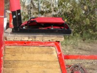
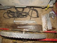
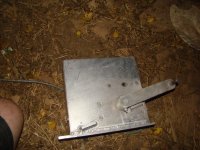
This is the new switch panel; it's the end off an ancient crystalyte analog controller, nice thick aluminum. Right now it's just got zipties holding it on. Drilled six holes for six toggle switches. Left the led and the original pushbutton on there, but they're not used right now. ATM it's just the canopy/deck lights and the headlight lowbeam setup on there. The early-1970s on-off-on switches (saved off a refrigerator-sized input panel from an unknown room-sized computer) are siliconed on the back to keep water off the wiring and keep the wires from being pulled or vibrated at the joints. (the panel itself was used as the deck for my Mk I kennel trailer for Hachi and Nana; not sure if I still have it).

dsc08388.jpg

You can see the back of it in the pics below, which also show the elastic wraps from Grin that cover the ugly wiring I can't pass thru the tiller tube.
dsc08401.jpg
dsc08402.jpg
dsc08403.jpg


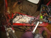
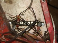
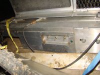
This is the revamped front triangle, with the redone wiring loom. It still looks messy at the bottom, and it *is* a lot of wires, but it's a lot easier to deal with, and to figure out what is where and troubleshoot something or modify things. I need another ground spade lug row, though...and I'm considering rearranging things to move the DC-DC in the top right, up to across the top, and the headlight and main power relays and turn signal blinker to just under that. THen move the bus block to above the wiring (instead of behind it) so it's easier to work with.

dsc08393.jpg
dsc08394.jpg


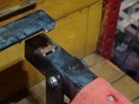
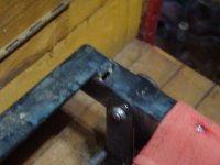
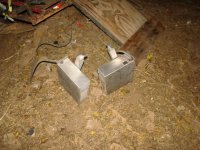
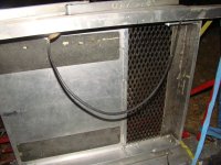
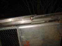
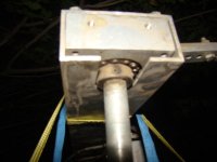
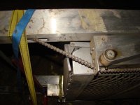
The rear speed sensor (other side is the same)
dsc08400.jpg


The front fork, with the new turn signal strips
dsc08390.jpg
dsc08391.jpg
dsc08392.jpg


The new rear DOT turn signals
dsc08395.jpg
dsc08396.jpg
dsc08399.jpg


I have "matching" front ones (actually they're rears, but I prefer the rear style in front and the fronts were easier to mount on the cargo box) but I have to take the mirror unit off the top, and build an angled mount to bolt them to above the headlight, under the mirror unit, and remove the old signals (and probably their angled mounts). Dunno when this will happen.
dsc08409.jpg
dsc08410.jpg


The Grin Tech headlight (12 LEDs) is slowly failing; the top row has stopped working and the bottom row blinks and flickers a lot.
dsc08408.jpg


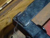
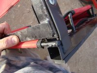
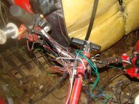
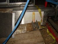
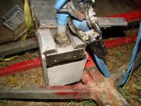
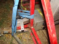
The wiring change on the rack, putting it thru the tubes instead. Wouldn't do this on the structural frame, but this part is mostly a style part of the trike, thin aluminum cot tubing, only "used" for long cargo like wood planks, tubing, etc., that can't be carried in the cargo area or on the rear cargo deck. Not made for significant weight, anyway, since the canopy would hold the other end and is unsupported at the front.
dsc08404.jpg
dsc08405.jpg
dsc08406.jpg


Now that there's no switches on it, just the lighting pack charge port, I'm going to make a cover for the twin tubes here, that run down the back fo the front triangle.
dsc08407.jpg

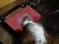
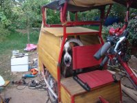
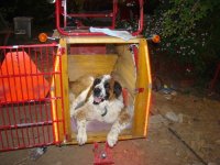
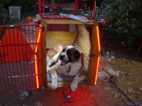
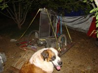
Last but not least, Kirin stayed with me every day most of the day out there, usually staying in the trike itself if she couldn't be right next to me up against me (since I was usually moving around, getting up and down, etc).
 

Attachments

  • dsc08411.jpg
    dsc08411.jpg
    58.3 KB · Views: 3,449
  • dsc08412.jpg
    dsc08412.jpg
    51.2 KB · Views: 3,449
All I really got done today was the new side cover for the wiring area, gorilla-taping the open "split tube" section on the back of that area until I can make a cover for it, and reinsulating the cargo seatbox inside, and cleaning up my mess (tools, parts, and wires everywhere, some of them helpfully carried around the yard randomly by the puppies; I know Yogi and Kirin won't do that, but PB & J still sometimes do).

But trike is rideable for work tomorrow, and any little stuff I find to be a problem might be fixable in the two regular "weekend" (weekmiddle, really) days off I have after that.
 
I forgot to add the pics of the new cover, so:
dsc08413.jpg
dsc08414.jpg

This cover is split just above the BB, using the old cover's bottom end for that part, and the new cover is thicker plastic cuz I dind't have any more of the same stuff I used before. Used regular bolts out of one of the HF boxed sets instead of the allenhead bolts I'd used before, cuz the HF allenhead boxed set I have doesn't have any long enough in the right thread size to fit the rivnuts I've got (#10 IIRC).
 
For unknown reasons, with the system reduced to just one 1.000mohm Grin Tech shunt, and set that way in teh CA Calibration menu, it only reads half the current that's actually flowing. Since it worked fine with 0.500mohm in teh menu in High Range mode with the two shunts paralleled, either I've done something wrong somewhere, or something has gone wrong in the CA itself.


Another anomaly: Even though the presets are identical except for the speed limit (5, 10, 20mph), with pass-thru throttle, the PAS operates differently in the 10mph preset vs the other two. (well, hard to tell in hte 5 becuase of the speed limit).

In the 20mph mode, when it reaches about 11 to 13mph (varies), the PAS fades out the motor power, and the trike begins to slow down. In a few seconds the motor stops powering at all, and speed continues dropping, till I reach the point where pedalling is the only thing moving the trike forward. If I stop pedaling of course it will also stop PAS, but...the PAS process of the CA is not sending any throttle signal out at that point (via the Diagnostics screen).

If I reverse pedal rotation just an instnat, and then pedal forward again, the CA resumes outputting throttle, and will engage the motoor and speed up again, until it reaches around that same speed again, then rpeates this process over and over.

If I reverse and forward pedals just after it startst o fade out instead, then it stops fading and continues throttle like normal, just for a second or two, if I keep doing this over and over I'll evnetualy reach 20mph where it will begin limiting speed. But I have to keep doing this, just pedalling forward regardless of cadence doesn't work like before.

The 10mPH preset it works like it should, and keeps me going at about 10mph, but without the surge up to 11-12mph+ and back down to 7-8 and cycling around that like it did before.

The 5mph preset goes up to 5, then sort of fades down but it's not like with the 20mph preset. it's likely that it is becuase the 5mph speed limit is hgiher than the point it stops assiting at. (but so is the 10, so...dunno).

Anyway, i'e not had a chance to play with settings to see what the deal is, or troulbeshoot the current measurement problem; no idea if they're related, or separte, or what could possibly be causing this stuff.


Right now it feels like the problems are multiplying rather than getting solved, and it's getting pretty stressful, especialy because at htis point there is no useful regen braking occuring in the right motor system, and none at all in the left.

This trike is heavy enough to *need* regen to slow it down quickly. I cna slow down wiht just the mechanicla brake on hte fornt hweel but have to do it gradually; a quick stop isn't possible because it'll skid the wheel and hten I don't have steering control; if I have to slow during a turn it's difficult at best, so I pretty much have to approach all turns at walking speed or less just in case...which is difficult and even dangerous in traffic.

I really want the proportional regen, the sinewave operation, etc., of the Grinfineons, the ability to do torque PAS control of the system with the CA, etc., but when these problems actually make it dangerous to ride normally in traffic for my work commutes, etc., it's getting to the point I may have to take them off, and use the CA only for monitoring, and go back to the generic controllers that while they don't have sine or proportional regen, or the warranty backing of a good company, at least regen works.

So...i'm going to have to fix the halls in at least one motor, and see if that fixes the no-regen controller. If it doesn't, i'll have to get hold of Grin to see what they can do about it, since regen is critical to this setup.

THen i'll have to see if proportional regen is significantly stronger than the on/off regen, becausei that's supposed tob e half power regen, and if it really is, then proportional regen won't be *nearly* strong enough to be useful, if it's only a max of twice what the one controller that does give any regen can do. If that's the case, these controllers are useless, and a waste of way more money than I can afford to throw away. I hope that's not the case.
 
I didn't get to do any of the configuration testing and such needed to determine the above issues' root causes yet.

Today I spent helping out a friend remove a broken powerchair lift from his old van; he gave me the lift itself because I can use many of the parts from it, both mechanical and electrical (it even has stuff to open and close the rear doors automatically). I guess the relays in it (large sealed types) tend to fail, and the repair center cant' get parts for this decades-old system anymore. (dunno why they wouldn't try sourcing alternate parts, but I guess they just didn't want to?).

Anyway, it's rather large and heavy, ATM it's tied down to the big MK IV.5 trailer, I'll post pics of it once the camera is recharged (later tonite if possible).

I'm considering finding someone that needs one and is willing to figure out what's wrong and repair it, and sell it for whatever I can get out of it.

But it has a lot of parts I could use for projects....
 
Pics of the powerchair lift. It's not all that clear, dark out htere except the flash. One pic shows a pinky-thick cable in a bundle; that's longer than the late 80's full sized van it came from, and is 4AWG. I guess if I need thicker battery cables.... ;)

Anyway, I won't have time to explore what's inside it for at least a few days, so here's the pics I've got so far.
 

Attachments

  • dsc08421.jpg
    dsc08421.jpg
    60 KB · Views: 3,387
  • dsc08420.jpg
    dsc08420.jpg
    59.8 KB · Views: 3,387
  • dsc08419.jpg
    dsc08419.jpg
    48.8 KB · Views: 3,387
  • dsc08418.jpg
    dsc08418.jpg
    49.1 KB · Views: 3,387
  • dsc08417.jpg
    dsc08417.jpg
    48.6 KB · Views: 3,387
  • dsc08416.jpg
    dsc08416.jpg
    53.2 KB · Views: 3,387
  • dsc08415.jpg
    dsc08415.jpg
    67.1 KB · Views: 3,387
  • dsc08427.jpg
    dsc08427.jpg
    53.8 KB · Views: 3,387
  • dsc08426.jpg
    dsc08426.jpg
    32.1 KB · Views: 3,387
  • dsc08425.jpg
    dsc08425.jpg
    27.9 KB · Views: 3,388
  • dsc08424.jpg
    dsc08424.jpg
    62.7 KB · Views: 3,388
  • dsc08423.jpg
    dsc08423.jpg
    68.5 KB · Views: 3,388
  • dsc08422.jpg
    dsc08422.jpg
    41.6 KB · Views: 3,387
Oh, I forgot that I did get one thing checked out on the CA wierdness:

The problem of it only seeing half the current was that I had forgotten to disconnect the sense wires to the other shunt, and that still left them paralleled though with tiny little wires (the blue and white ones in the CA-SA shunt). I don't see how that would cause half current to show up (without melting things), but it did, cuz as soon as I cut the sense wires to the disconnected shunt, the current went back to normal (tested only during charge so far, but it ahd been reading 5.99A, now it reads the 12A it should).

Nothing on the other issues yet.
 
The headset has felt a bit loose ever since installing the new fork; the cargo strap "clamp" never did quite tighten it enough, and I haven't gotten back to it. Today I got off work an hour early, so thought when I got home I'd just fix that real quick using some adjustable bar clamps, and install a star nut in the steerer and make some tube rings to let that help clamp it too.

This also required taking the headlight assembly off to undo the bolts clamping the tiller to the steerer, and when I did that I could see a further consequence of the crash; the "toptube" of the old Murray (IIRC) bike that was used for the headtube/toptube/downtube partial triangle section at the front of the trike, cracked completely away from the headtube, at the base of the weld of the toptube.
dsc08451.jpg
dsc08452.jpg
dsc08454.jpg


Since the downtube (the 2" square tube that becomes the keel past the cranks) is welded to the headtube, with the original downtube of the murray inside it, also welded to it thru holes here and there, that doesnt' appear to have any issues, and prevented complete failure.

So I took the side panels off (which requires drilling out the rivets on the right side) and covered the wiring so the welding wouldn't damage it, and rewelded the toptube back to the headtube. Then reriveted the right side panel back on and bolted the left on.


Crack fixed, I fixed up the headset (which was indeed still a bit loose; it wasn't just the crack causing what I felt during braking. So now it should be good.

All that took over two hours....


Another problem I've had for the last couple of weeks is the pedal chain just derails off the input sprocket to the IGH while pedalling, or backing the trike up. Haven't had that problem for ages, so couldn't recall what caused it. Kept meaning to look thru this thread to find the old posts, but forgot; too tired usually after work. When the problem first started this time around, I was just leaving for work and hte shifter cap popped off and the rod fell out. I put the rod in the house and went to work, not having time to deal with it, and forgot about that, too.

Today the chain wouldn't stay on there at all; always derailing to the outboard side. The zillionth time I put it back on I saw what I thought was the reason--the right rear tube of the stays from the dropout the IGH is mounted in inside the frame in front of the seatbox had separated from the seatbox frame, about a quarter inch from the weld, probably from the stress of holding the trike halves together back whent he keel broke.

dsc08453.jpg

Couldn't do anthing about that then, so did it atfter fixing the stuff above. The reweld was easy, but it didnt' fix the problem...looking closer I found the input sprocket side's bearing cone had actually unscrewed, pushing the other nuts and whatnot outboard...it wasnt' really the cone that unscrewed it was the axle that had turned within the unit and caused evertying to unscrew. I don't know why, as there's a big fat tabbed washer that sits on the axle flat section, and the tab is in the deepest part of the drpout, and all that was tight...yet it did it anyway.

There's nothing else I can do ot prevent that, so I just reassembled it the way it should be, and hoped none of the bearings had fallen out (they might have, but I didn't have time to take the IGH out of the frame and open it up to check).

The freewheel doesn't work in it now, so something is messed up in there, but it works in the default gear (1:1?). Thankfully there's a freewheel at the rear wheel. I dunno if I can fix it or not, but I have other IGHs if I can find their shifter stuff. I have another of these (shimano 333, IIRC) too, somewhere.


Because of other problems, with the CA PAS setup, I disconnected the PAS/torque sensor from the CA a few days back; it's just too dangerous with it kicking in at the sligthest touch of the pedals (whcih it shouldn't be able to do, since the CA requires significant rotation of the cranks to begin applying power, according to it's design...just that it isn't doing that correctly anymore, and I have no idea why).


So for now the trike is throttle-only for the motors, independent for left and right, with the right going thru CA in pass-thru mode, but still with the 3 presets for speed limiting 5, 10, 20mph.


Wish I could get another vacatino soon, to work on all the zillion other thngs that need fixing, but probably can't until November, maybe October if I'm really lucky. :/
 
Back
Top