The SB Cruiser : Amberwolf's 2WD Heavy Cargo Trike & Dog Carrier

amberwolf said:
Lately I've been having good results from Specialized brand innertubes.
Do they make 20x2.5 thickwall tubes with a TR-6 threaded valve stem?
Sorry, not sure. I got them from FLBS when I was suffering the "evil innertube syndrome." Happily they had the size I needed (26 x 1.75-2.4), decent price (esp. from brick and mortar store). They felt substantial, the rubber felt and looked fresh, 40mm schrader valve stem was securely implanted, installed easily and have been trouble free for several thousand miles since.

Heard good things about Kenda thorn-resistant (read thickwall) but haven't tried them yet.
 
Leaving myself this link
(edit: new xf version link The SB Cruiser : Amberwolf's 2WD Heavy Cargo Trike & Dog Carrier )
to a 2017 post about the leftside chainline vs axle vs dropout position so I will remember to work this out whenever I get around to swapping out the MXUS to the Ultramotor.


The chainline (very short, just a few inches) from the output of the pedal drivetrain to the freewheel on the motor only lines up with the MXUS because I modified the MXUS to fit it. I'm guessing this is because I originally used a modified *front* motor on that side, since this whole trike kit that this trike is based on was built for "front" wheels (or rather, single-speed wheels, which are very similar axle spacing).

So I need to move the inboard dropout inward some distance (half inch-ish) to ensure the chainline is correct; this may also mean modifying the fender frames on the inboard side to clear the tire. (I could modify the axle on the Ultramotor...but since half the reason I am using the Ultramotors is because their axles are stronger/better made (since I've broken axles on other types under conditions where the UM damaged the clamping dropout instead), I'd rather not screw that up by messing with them).
 
Last edited:
Since the new tubes arrived the last several days, I need to change out the patched tube (which still slowly leaks; goes from 35PSI to 20PSI in about five days). Been carrying (inflated inside loose old tires so I can easily tell if they're still aired up or not) spare also-patched tubes in the back of the trike, but I don't trust them, either.

(I wish solid "air free" tires actually worked without destroying wheels and giving such a harsh ride I doubt even the trike would survive it over time).


I've had to change my route to work and back home because there are multiple destruction and construction projects leaving potential debris that could take out my tires (or wheels!). The major construction project has been going on for nearly a year and is probably going to last that much longer from what I've seen so far. The destruction project only took a couple of weeks but the area is still covered in debris bits especially where I have to ride, so I avoid as much of the area as I can.
 
Between the hot weather and not feeling well far too often, I haven't yet changed out the tube(s), but have kept them on the trike with me in case I need one when out.

I also kept a couple of patched tubes, partly inflated inside old tires, in the bakc of the trike.

But so far the patched tube in the left tire has been mostly ok; it has a very slow leak requiring air every couple of weeks or so (depends on temperature change range, mostly).


There's a new problem, though (actually several, but some has been a while coming on slowly): The main power to the lighting (everything, including brake lights and turn signals) intermittently and randomly turns off, very very rarely. I have tested and examined every wire and connector, and the switch used to to turn on the steady lighting (which doesn't control the turn signals or brake lights), and the relay that turns the lighting power on and off (controlled via a DC-DC that just powers teh relay coils any time the main traction batteyr power is turned on), and found no problems, but obviously one exists somewhere.

It's a mechanical issue somewhere in the "triangle" of the front frame section, where the majority of wiring, and the relays and the DC-DC are, because when it happens while riding, I can gently smack the side panel with my heel and the lights come back on. Sometimes they come back on on their own, right after going out.

I suspect that there is an issue with the DC-DC itself, perhaps a broken solder joint, or the relay coil (or it's socket) but there is no sign of either one I can see, or find with a meter. I'm considering putting a pilot light on the bars powered by the DC-DC so I can see if it ceases outputting when this happens.


While testing for the cause of the above, I fixed some other stuff:


The front brake has been intermittently rubbing when I turn or am on a crowned road so the trike is tilted over to the right. I couldn't feel anything for wobble, etc., but when I took the wheel off, I found the axle bearings were just a hair loose. The cone nuts had backed off a tiny amount, so I readjusted them and retightented the locknuts, such taht the wheel spins freely with no bearing grab but it has no wiggle. Now there's no rub, and the wheel spins better, too; the whole trike feels like it just rides better. :)


The righthand front turn signals on the fork (but not on the bars or body) went intermittent some months back, and then stopped entirely, but I couldn't find the broken wire in my quick checks back then. Since the other signals sitll worked on that side I didn't worry about it, but since I had the triangle open I metered the wires and eventually found the break...right where teh wries bend on every steering action. None of the other wires were damaged this way, but *both* the ground and signal to the fork signal ligths on the right side were broken. Spliced and now they work fine.


The IGH shifter hasn't worked right, well, ever. It takes so much cable tension to pull the shifter chain out that it's nigh impossible to actually move the lever enough to pull the cable. This is because the angles of things on the frame to the IGH end tube the shifter chain comes out of are extreme--greater than 90 degrees (probably 110-120). The shifter chain "grabs" on the edge of the end of the IGH's shifter tube, regardless of orientation, unless i is pulled virtually straight out. I don't know why it isn't designed differently, so that won't happen, because on any bicycle there's literally no way to pull it out that way. On a trike, especially one that uses an IGH in the left wheel, the cable to the chain could be setup easily to pull straight on it. Mine is a bit different, but if I put a tube sticking out of the bottom of the seatbox frame at the correct angle and length, the cable pull for this can be bolted to it and it will work just fine.

Until then, I screwed the cable pull to the seatbox wood at teh best angle I can make for it, and moved the shifter itself to the "downtube" (rear upright of the triangle) where I actually had it some time back, to give enough cable length to have the shifter cable pull where it is now without changing the cable, since for this the cable must loop around under the cargo/seatbox before going up to the shifter and cable stop. Some pics are attached to the end of the post.


When I opened the triangle up, taking the left plastic panel off, I found that the left vertical tube at the back fo the triangle is cracked all the way thru--it is the source of the squeak I could not locate all these months (as far back as a year and a half ago or more). I suspect it was fractured in the fork-breaking crash some time back, and eventually broke all the way at some point from the side-to-side flex/twist the triangle gets during turns from the forces passed thru the area from the front wheel to the rest of teh trike. Since those uprigths are not really structural, it shouldn't make much difference if it's fixed or not, but I'll fix it at some point.

Since welding it rquires removing the plastic off teh other side, and coveirng all teh wiring/etc in the triangle, it will probably take up to a few hours to fully prepare to weld just that little bit. Since I also want to weld on a tube for a derailer on the front, which also requires doing all that, I'll wait till I'm prepared to do both, and to weld the cablestop holder for the IGH on the cargo/seatbox's lower frame.
 

Attachments

  • 20220725_115102.jpg
    20220725_115102.jpg
    2 MB · Views: 1,825
  • 20220725_115110.jpg
    20220725_115110.jpg
    4 MB · Views: 1,825
  • 20220725_141410.jpg
    20220725_141410.jpg
    2 MB · Views: 1,825
  • 20220725_141415.jpg
    20220725_141415.jpg
    4 MB · Views: 1,823
  • 20220725_141434.jpg
    20220725_141434.jpg
    4 MB · Views: 1,824
  • 20220725_141444.jpg
    20220725_141444.jpg
    4 MB · Views: 1,824
The Kenda tire that came on the A2B Metro motor presently in use on the rightside of the trike has been doing what every Kenda tire I've ever had does--the sidewall is disintegrating, flaking and peeling off.

It never seems to matter what bike I have them on (big, small, heavy, regular, etc), what PSI I run them at (vs their "rated" PSI), or what kind or size they are, etc., it's just something about how Kenda makes their tires. (I can't recall it happening to any other brand I've used, but every Kenda it has.)

Until it started happening (weeks ago, probably closer to 3+ months, maybe even four) I was starting to think I liked the way it cushions bumps.

But I don't like the bounciness it causes on that side, and it's much less sticky tread compound that does not have much grip. Because of that, I can skid / drift that side of the trike, which I cannot do so with the Shinko tires even when they're brand new or when worn out. Skid/drift can be fun under the right circumstances, but it makes the trike hard to control in traffic when I have to make avoidance maneuvers for either road debris or damage, or misbehaving traffic. It's worse in even slightly wet conditions, by enough to make it actively dangerous.

I've tested out the regen braking back there a couple of times, too, because of wet conditions taht prevented the front wheel from having enough grip to stop me quickly enough, and that tire just skids out (a Shinko on the same wheel grips fine, as it does on the other wheel).

So I need to change the tire out on this side, to a Shinko. I should do this this weekend before it rains again....

The Shinko's aren't as good at absorbing the bumps, partly because they are smaller in air volume (I'd guess half the volume), partly because the whole tire is harder / thicker, vs the Kendas which are pretty flexible and thin-side-walled.

Interestingly despite the thinner tire and that it is on the right side where much more road debris / etc is, I haven't had any flats on that tire, though it has developed a slow leak I have to re-air every 3-4 weeks (loses about 7-10psi in that time, out of about 35-40).

If I ever get around to rebuilding the rear wheel wells to hold bigger tires properly, I'd switch to 3" shinkos (the SR714-80/90, I think it is, vs the SR714-16/2.25 I've been using), and that would likely help a lot with the bad road bumps/holes I can't avoid riding thru.
 
So much for no leaks or flats on the Kenda. A mesquite or paloverde thorn took it out on my ride home from work Saturday, though it plugged the hole well enough that it didn't go flat enough for me to notice until Monday midday. I haven't pulled it out of the tube yet but it's probably > 1cm long, I've seen them over 4-5cm long on some of the trees, and easily 2-3mm thick; I have sewing needles that would feel inadequate in comparison.


So since the tire was failing too (sidewal problem noted before), I just swapped out the whole tire/tube for one of the two spare tire/tubes I have been carrying on the trike for such an instance (expecting it to happen on the road, which thankfully it has not), so now it again has the 2.25" Shinko SR214s' on both sides, and doesn't ride lopsided anymore (the Kenda is so much larger that the trike was significantly higher on the right side--so much so that on the steepest crowned roads I would be riding level, and on flat roads leaning left).


WHile I had the trike on it's side, I also fixed another problme that had started perhaps the week before: The cotter pin that secures the transfer-axle input sprocket to the shaft sheared off, on the pedal drivetrain. Given that I am not putting much pedal power in, just enough to start moving from a stop such that the motor then engages via the cadence-controlled PAS via the CAv3 (when I am not using the throttle to do that instead, and then pedalling along but not applying pressure), I'm surprised there has ever been enough torque against this pin to do this, even though this trike is probably 3-4 times heavier than what the ancient Schwinn "trike kit" was intended for.

The grub screw 90 degrees around from the cotter pin wasn't enough to be able to keep the sprocket from spinning on the shaft without the pin, so after this the pedals would freely spin even when completely stopped.

This was actually helpful, in that it meant I could startup from a stop without the usual leg, knee, ankle pain, but of course it also meant that in the event of motor system failure I would not be able to pedal home (albeit at a very very slow speed, <1mph). I debated with myself on fixing this, just because it made the startup so much easier.

What finally decided me was that while the sensored Grinfineon on the left motor doesn't have a problem with driving the motor forward even though it might be rolling backward a bit (like if I let go the brakes at a stoplight where the road goes uphill very very slightly to the intersection and the trike rolls back until power starts), the generic sensorless controller on the right sometimes stalls out and shutsdown under this condition. When that happens, it cannot restart until I either power cycle the system, or come to a complete stop for a second, then use the ebrake to reset it (why that resets this condition, I don't know). The GF simply doesn't have enough power by itself to get me moving very quickly, and takes the entire intersection to get me to even 10mph, something on the order of 10+ seconds, which means I'm in the way of any cars/trucks behind me at the light and they get rapidly impatient, which sometimes mean they do unsafe things.

Since using the pedals (when they also push teh trike mechanically) to startup from PAS or at least hold position to prevent rollback as motor starts up from throttle means that shutdown situation doesnt' happen, I decided to go ahead and fix the broken pin.


Not having a new cotter pin, or the proper tool to get the broken one out, I located a 5mm allen wrench (I have a lot of them in that size, as they come with a lot of user-assembleable items) and hammered out the cotter pin with that...it happens to be such a tight fit that I left it in there as a replacement, just slightly bending it so it can't fall out. I'll recheck it for shearmarks at some point, to be sure it won't fail without warning. I also put a couple spares in the toolkit in case it does so I can hammer a new one in. :)


Hmm...cant' seem to connect to the phone to upload the pics; I'll edit this to add them in once I figure the problem with that out. :/
 
The cracking in the tire carcass:
20220928_163209.jpg20220928_163232.jpg20220928_163236.jpg20221003_130506.jpg
20221003_130518.jpg20221003_130539.jpg
The mesquite or paloverde thorn in the tube
20221003_130656.jpg


The cotter pin problem, and the broken pin. I seem to not have a pic of the allen wrench in it's place.
20220928_163135.jpg20220928_163142.jpg
20221003_145937.jpg


The axle of the UltraMotor, and the grooves it's threads carve into the thick steel dropouts (even the pinching ones that clamp the entire length of the axle!), upon regen braking...shows how good the UltraMotor axles are, vs the MXUS, Crystalyte 5304, etc., because those axles broke or sheared off under the stress of braking/acceleration, without damaging the dropouts...but the UM axle is undamaged, while the dropouts are deeply scarred; the UM axle is hard enough and strong enough to be able to twist inside the dropouts (even the clamping part) as it's edge cuts into the dropout steel. (you can see the shininess of the cuts).
20221003_130756.jpg20221003_130754.jpg20221003_130746.jpg20221003_130710.jpg
 
Couple days ago I was encouraged enough by the slightly cooler (low 90s) weather to fix the problem where intermittently, in no predictable pattern or situation, the lighting power would just fail. I knew it was within the "front triangle" where all the main wiring, relays, DC-DC, etc are, but couldn't find anything loose, etc., and it would never fail while I was looking at it or moving things.

The intermittent lighting power problem turned out to be the input to the DC-DC (which is really just a 15VDC SMPS type wallwart). When I set it up a few years back, I was going to just push spade lugs over the AC input terminals, but they were too thick for any of the lugs that were the right width. I soldered mating spades to the AC plug prongs instead, with the prongs bent 90 degrees so they would be flat against the back of the housing.

One of those spades had gotten loose enough to cause a poor enough connection for the DC-DC to shutdown sometimes, but not loose enough to feel loose, or exhibit any visual symptoms at the connection. But at this point it had gotten loose enough to finally be able to cause it to fail while touching things inside the triangle, and tapping on the DC-DC itself would do it one in a dozen times or less.

I decided to just completely remove the terminals and spades and wires from PCB to the prongs, and the prongs from the housing, and run the supply wires thru the casing and solder them directly to the PCB. No connector to fail now. ;) No problems in the couple days of riding so far, where it had been at the point of 3-4 times a day of failing. Think it's fixed now.


Another issue I have had numerous times since I corrected the bearing locknuts on the front wheel a while back (a few posts above, I think), is while riding, especially after a sharp turn thru rough road surface (lots of right turns are torn up in the area, some down to the dirt under the asphalt, which is very deep--I have to avoid those holes or break a wheel or just plain get stuck in the hole), the front end would feel wiggly, because the QR skewer had flipped open (even if I had it pointing downward, and had had to use significant force to close it previously).

I never had time to troubleshoot this while riding, and would forget by the time I got home, but happened to rememeber while fixing the DC-DC above.

So I carefully examined the dropouts, skewer, axle, etc., and found that while nothing had loosened, the way the dropouts are made, if I seat the axle fully, then tighten the QR nut then begin to flip the lever, it pulls the lever end out of the dropout just slightly, and it ends up just on the edge, just barely, of the lawyer lip at the bottom of the dropout. If you're not staring right at it as it happens, you don't even notice. So...what's been happening, most likely, is that the force in the turn pushes the axle up just that tiny bit and the QR nut pops off the lawyer lip and instantly loosens the QR.

Why it never caused a problem before, I haven't a clue.

So I carefully ground the edge of the lip around the recessed area the QR nuts fit in, just at the very bottom end, to remove the teensy part the QR ends up stuck on. Now this doesn't happen, and it should prevent the problem with the QR coming loose. So far, no problems in the couple days' riding, but the problem has been rare an intermittent, so we'll see.

FWIW, I suspect this is actually the cause of the locknuts/bearing issue as well, but I don't really know.
 
BTW, the axle on the rightside wheel has already begun to rotate in the clamping dropout; it's probably >30 degrees now. I haven't even used braking; it's just the torque from startup. :(

I'm going to have to take the clamp apart (requires cutting it off the frame) so I can weld across the areas where threads have cut into the metal, then reflatten it, and see if I can improve the clamping mechanism to more securely hold the axle flats.


It is interesting that they were sufficient to hold the crappier-made MXUS axle even with the SFOC5 controller (much higher power than the generic thing I have on there now), such that the axle itself broke before the clamp would let go...but the Ultramotor axles cut into the metal instead and rotate.

Now, I'm not really complaining--I'd MUCH rather have the axle remain intact because it's a lot easier to fix and modify the frame. ;)
 
Soooo.... this happened:

I was almost home, 1/8th of a mile or less, wehn there was a BANG!!!! from the right rear, as loud or louder than the time the SFOC5 reversed direction while I was riding at full speed back when I was testing that with the MXUS (it broke the axle, then). I didn't know what happened this time so I stopped as quick as I could (no traffic, thankfully). No tilt to the trike unlike when I have a flat, but felt very wobbly (like a flat) as I slowed to a stop.

Got off, and looked, didn't see anythi...oh shit. :shock:

20221014_154544.jpg

Almost half the spokes on the wheel had virtually simultaneously snapped (there had been no problems and no noises or other symptoms until that BANG!, so I think one let go and the sudden change in tension on others just snapped them in a row). All the outboard spokes are intact (well, they're not broken), however all but four of the inboard spokes are snapped, every one of them at the threads just inside the nipple. :(

More pics of the damage at the end of the post.

I have no idea what kind of spokes these are; they came installed on the wheel; probably they are original OEM from the A2B Metro factory setup (I also don't know what kind of stress they have had to endure before they came to me, where they are probably being stressed far more than in their original usage.

When I got it it was true and appeared to be correctly tensioned (based on experience rather than a tensiometer as I don't have one). So I don't know the cause of failure. My best guess is the threads were cut too far down the spoke, not threaded fully into the nipple, so eventually fractured there--there are at least a thread or two showing on the broken ends of the spokes I looked at closely. All the spokes are present, hanging in the flange holes, so none of the J-bends broke.

Why the inboard side all went, and none of the outboard? there's another mystery....best guess, again, is the threading vs spoke length--I'm going to check when I get some spokes out of it to measure them, but I bet that the outboard spokes are all fully threaded into the nipples (or at least, threaded further in than the inboard were).

Note that on this side of the trike, inboard is the "drive side" of the wheel, and outboard is the "brake side", since it's flipped vs the left side of the trike where it works like a regular bike drive side/etc.


I have to work tomorrow, and am already exhausted from working today, so I just swapped in the other Ultramotor wheel I originally swapped this one in for, the one that has the damaged rim (but all intact spokes). If I had the energy and time I'd relace into a new rim with the spokes already on it, but I don't; I kept putting that off much of this year so far (was part of the point of getting this UM wheel to have one on the trike while I relaced the other one...oh well).

In the process I took some pics of the axle hardware, including this of the outboard "bafang" torque washer (from the Jump bike motor), which has cracked next to the torque tab.
20221014_161012.jpg

The twist of the axle from the outboard side (note the cracked torque washer is still in the dropout correctly...)
20221014_160248.jpg
20221014_160539.jpg


The inboard washer is intact, but it somehow managed to be pulled outboard along with the axle itself far enough to pop up and over the dropout lip and drag thru the steel leaving this gouge mark. I had no idea these torque washers were that much harder than the thick steel plate my dropouts are made of...but they are. I don't know when this happened, it could've been anytime since I changed the tire in one of the posts above (couple weeks ago?).
20221014_163832.jpg


I put a not-really-any-better "torque washer" from some other hardware kit into the inboard side, and put the other bafang tw on the outboard side; neither one is likely to do any good; I'll have to re-face the dropouts and rebuild the inboard clamp to fix this issue. Not happening today.


Is now back together and working...PITA though. :/

Jelly Bean The Perfectly Normal Schmoo got tired of waiting for me to be done long before:
20221014_160426.jpg


Now I need to measure the unbroken spokes and order some more from Grin Tech, or maybe I'll first try out that Z-bend trick over here:
https://endless-sphere.com/forums/viewtopic.php?f=51&t=117942
I should have plenty of long-enough spokes to work with from old projects.
 

Attachments

  • 20221014_154556.jpg
    20221014_154556.jpg
    4 MB · Views: 1,472
  • 20221014_154559.jpg
    20221014_154559.jpg
    2 MB · Views: 1,472
  • 20221014_154636.jpg
    20221014_154636.jpg
    4 MB · Views: 1,472
  • 20221014_154639.jpg
    20221014_154639.jpg
    4 MB · Views: 1,473
Failure analysis time:

I disassembled the broken wheel,and took as good a pics as I could without breaknig out the magnfying workstation camera. I will do that later to get as good a pic of the broken ends as I can; maybe see if the broken surfaces indicate the type of failure mode that happened.

Pics are at the end of the post rather than inline to make it easier to find and read the text itself.


All of the broken spokes are straight, except for the one that was jammed between the inner circumference of the rim and the spoke flange, and was bent by this--it's bent parallel to the axle rather than along the rotation path, so the bend is almost certainly not from an impact during rotation (there wasn't anything it could have hit, anyway).

I can't tell which spoke let go first, but I still think that one must have failed, then the others all "unzipped" after it so rapidly that it sounded simultaneous, making the BANG! I heard.

Measurements were done with a cheap electronic caliper.

Orignally I thought the spokes were straight, unbutted, but taking closeup pics they appear to be single-butted spokes, with the thicker part (2.1mm) ending on a sloped size transition before the start of the threads, transitioning to 1.8mm just prior to the threads for ~1 to 2 mm (varies on each spoke, broken or unbroken). It's probably not from the threader; I've never seen this kind of sloped transition at the end of threads on other spokes, but I do see it on butted spokes at the butt (size transition) itself.

Unbroken inboard spokes were 94.2mm to 94.5mm long from far end of elbow to far end of threads. Outboard spokes were 96.1 to 96.3mm.


AFAICT, almost all of the breaks are at as close to the same point on the threads as makes no difference, with a couple of exceptions, this appears to be the point at which the threads inside the nipple itself end but I am not certain of that as I can't clearly see down into the hole. I also haven't figured out a way to remove the broken-off part of the spoke from the nipple without damaging one or the other (to put them all side by side and see if they actually are the same amount of thread, for instance).

There is some brass nipple thread left stuck in the spoke threads of some of the broken spokes, indicating that when they broke and pulled out of the nipple they sheared some of those off.

All four of the inboard spokes left unbroken have some small (1-2mm) gap between the end of the nipple and the thicker part of the spoke, leaving some thread and the tiny unthreaded portion of the thinner part of the spoke visible.

Most of the outboard spokes have no noticeable gap between the end of the nipple and the thicker part of the spoke (though some do).

Test-fitting nipple and spoke pairs for the broken ones, one at a time as I took them off the wheel, most were like the unbroken ones, but a few had almost no gap.

Threading nipples onto unbroken spokes, they will only go on right up to the very base of the thicker part of the spoke. That thicker part will not fit into the nipple hole's unthreaded area (it hasn't hit the unthreaded part of the spoke on the nipple threads yet, and there is still plenty of room in the nipple's threaded part for the spoke to continue threading on, just the spoke is too thick at that point to go in any further).


I have a theory that may just be fanciful thinking, because there should be no way for the spokes to change angles relative to the nipples where they are not in contact with the nipples. , but:

For the spokes with a gap between the end of the nipple and the thicker section, presuming they can then move (change angle) relative to the nipple under cycling loading/unloading conditions, *maybe* this caused fatigue cracking along the cut thread line at the point where they're not supported by the nipple. If there was fatigue cracking already present on enough spokes, the failure of one could put sufficient load on the next to break it, and the load rapidly increases on the remaining spokes as they continue breaking, until the load is now removed from the last few by where they are in the rotation of the wheel, etc.

The spokes wihtout a gap there would not be able to do this, so they should not fatigue from that.

It's probably wrong, but it makes some logical sense, *if* there is a way for the spokes to change angles relative to the nipples where they are not in contact with the nipples.


Pics below show the first broken spoke and nipple in a few images, to try to see how far the spoke sat down in the nipple. Included are some apparent drill shavings that were trapped under the rubber rim band.

Then the broken spokes' nipples.

Then the broken spokes; in order from bottom / left that were closest to valve hole then "clockwise" around the wheel (outboard side facing me) to back to closest to valve hole, *except* the last two which were from the reflector about opposite the valve hole.

Then some pics of the unbroken spokes nipple heads still on the rim with the spokes in them, to attempt to see relative difference between those and the broken ones, if any, first of the ones on the inboard side, then the outboard after the next pics.

The next are of first an unbroken inboard spoke, showing the gap I was talking about. Then an outboard spoke, showing no gap.

Then some pics of the rim itself and it's labelling, and some nipple holes.

Then some pics of this rim compared to the ex-Zero rims my other wheels use.

Then the unbroken inboard spokes removed from teh rim, from left to right in order as tehy were on teh wheel.

Then the outboard spokes, in clockwise order from valve hole back around to there. Note that some have bends at the start of the threaded section; I am guessing that is from riding the broken wheel back home, but I can't know for sure.

Last is a pic of an inboard and then an ouboard spoke, showing how far each will thread into it's nipple.
 

Attachments

  • 20221016_132342.jpg
    20221016_132342.jpg
    2 MB · Views: 1,364
  • 20221016_132435.jpg
    20221016_132435.jpg
    3.6 MB · Views: 1,364
  • 20221016_132505.jpg
    20221016_132505.jpg
    3.4 MB · Views: 1,364
  • 20221016_132511.jpg
    20221016_132511.jpg
    3 MB · Views: 1,364
  • 20221016_132519.jpg
    20221016_132519.jpg
    3 MB · Views: 1,364
  • 20221016_132525.jpg
    20221016_132525.jpg
    3.1 MB · Views: 1,364
  • 20221016_132625.jpg
    20221016_132625.jpg
    3 MB · Views: 1,364
  • 20221016_132635.jpg
    20221016_132635.jpg
    3.4 MB · Views: 1,364
  • 20221016_132922.jpg
    20221016_132922.jpg
    3.4 MB · Views: 1,364
  • 20221016_132938.jpg
    20221016_132938.jpg
    3.2 MB · Views: 1,364
  • 20221016_133523.jpg
    20221016_133523.jpg
    3.1 MB · Views: 1,364
  • 20221016_133544.jpg
    20221016_133544.jpg
    1.5 MB · Views: 1,364
  • 20221016_133554.jpg
    20221016_133554.jpg
    1.4 MB · Views: 1,364
  • 20221016_133557.jpg
    20221016_133557.jpg
    1.4 MB · Views: 1,364
  • 20221016_133559.jpg
    20221016_133559.jpg
    1.5 MB · Views: 1,364
  • 20221016_133640.jpg
    20221016_133640.jpg
    2.8 MB · Views: 1,364
  • 20221016_133650.jpg
    20221016_133650.jpg
    2.7 MB · Views: 1,364
  • 20221016_133703.jpg
    20221016_133703.jpg
    2.2 MB · Views: 1,364
  • 20221016_133706.jpg
    20221016_133706.jpg
    2.2 MB · Views: 1,364
  • 20221016_133709.jpg
    20221016_133709.jpg
    2.2 MB · Views: 1,364
  • 20221016_133715.jpg
    20221016_133715.jpg
    1.8 MB · Views: 1,364
  • 20221016_133718.jpg
    20221016_133718.jpg
    1.9 MB · Views: 1,364
  • 20221016_133722.jpg
    20221016_133722.jpg
    1.9 MB · Views: 1,364
  • 20221016_133728.jpg
    20221016_133728.jpg
    2 MB · Views: 1,364
  • 20221016_133733.jpg
    20221016_133733.jpg
    2 MB · Views: 1,364
  • 20221016_133855.jpg
    20221016_133855.jpg
    1.6 MB · Views: 1,364
  • 20221016_134030.jpg
    20221016_134030.jpg
    2.9 MB · Views: 1,364
  • 20221016_134041.jpg
    20221016_134041.jpg
    2.8 MB · Views: 1,364
  • 20221016_134111.jpg
    20221016_134111.jpg
    2.9 MB · Views: 1,364
  • 20221016_134119.jpg
    20221016_134119.jpg
    2.2 MB · Views: 1,364
  • 20221016_134129.jpg
    20221016_134129.jpg
    2 MB · Views: 1,364
  • 20221016_134145.jpg
    20221016_134145.jpg
    2 MB · Views: 1,364
  • 20221016_134217.jpg
    20221016_134217.jpg
    2.8 MB · Views: 1,364
  • 20221016_134231.jpg
    20221016_134231.jpg
    2.8 MB · Views: 1,364
  • 20221016_134305.jpg
    20221016_134305.jpg
    2.7 MB · Views: 1,364
  • 20221016_134309.jpg
    20221016_134309.jpg
    3.1 MB · Views: 1,364
  • 20221016_134320.jpg
    20221016_134320.jpg
    2.7 MB · Views: 1,364
  • 20221016_134538.jpg
    20221016_134538.jpg
    2.5 MB · Views: 1,364
  • 20221016_134545.jpg
    20221016_134545.jpg
    2.8 MB · Views: 1,364
  • 20221016_140903.jpg
    20221016_140903.jpg
    3.2 MB · Views: 1,364
  • 20221016_141012.jpg
    20221016_141012.jpg
    1.6 MB · Views: 1,364
  • 20221016_142330.jpg
    20221016_142330.jpg
    3.1 MB · Views: 1,364
  • 20221016_142341.jpg
    20221016_142341.jpg
    2.1 MB · Views: 1,364
  • 20221016_142348.jpg
    20221016_142348.jpg
    2.1 MB · Views: 1,364
  • 20221016_142400.jpg
    20221016_142400.jpg
    3.1 MB · Views: 1,364
  • 20221016_142648.jpg
    20221016_142648.jpg
    2.8 MB · Views: 1,364
  • 20221016_142747.jpg
    20221016_142747.jpg
    2.7 MB · Views: 1,364
If it's fine to have a go by a rather unexperienced person to contribute to discussion, here is a few guesses.

- Lots of spokes giving up at once probably says it was too heavy for the wheel.
(or motor is too strong).

- Maybe connected to your theory, radial lacing may have something to do with this (and cause more fatigue)? Longer and crossed spokes maybe support better but probably not possible with this wheel & motor.

- This vehicle maybe have "lateral force" on wheels more than a regular ebike, and maybe the wheel was also in slight angle all the time that caused a fatigue. Snapping only one side may be also sign of that?
 
Thank you.

There's more details over here:
https://endless-sphere.com/forums/viewtopic.php?f=51&t=117942#p1736431
in a series of posts, if it's helpful.


FWIW, it's something specific about this wheel (that I did not build so no details on how it was done other than the analysis above and some speculation), vs any of the ones I did build...because none of them ever failed in any way similar to this one, despite being stressed far more under more weight and more extreme conditions than this has been during the time I have had it (I don't know how it was used before I got it, on the A2B Metro it came from).

It's certainly possible likely that the other wheels that didnt' fail are vulnerable to failure, and would eventually do so when the right conditions come along...but years of operation under higher loads and worse conditions with no problems vs this one's sudden failure with less loads and easier conditions in only a few months suggests strongly it's not a general overload problem with this "style" of wheel / number of spokes / etc.

My goal is to figure out, if possible, what specifically about this wheel caused the failure, both because I just want to know, and because I want to ensure this type of failure never happens in any wheels I build (even though it hasn't happened yet, it's always possible if I don't know why it happened to avoid it). :)

Weight is something I've had various ideas about but have not been able to build the new version of the trike to test them out (they can't be done on this one because I need it operational all the time and it requires major reconstruction to do them). Doubling the number of spokes could be done on this one, but ATM there isn't a compelling reason to do that given prior history before this wheel. I'll probably do it as a test anyway, once it's possible.

This size wheel would require modification of the rim (dimpling it) to angle the spokes for anything other than radial. Otherwise it will place stress at the nipple exit, which has certainly caused spoke breakage at the threads in other wheel builds.

Lots of lateral force (side loading), is unavoidable here. I built a trike for my brother, the "Raine Trike" that has it's own thread around here somewhere, that uses cambered wheels to attempt to reduce this, but since he used it maybe two or three times and then just never bothered to even touch it, I don't know how that changes performance, just no data. (they are also 26" wheels with smaller geared hubmotors, so couldn't be directly compared to this one).

All of these things are probably


Some thoughts to compare this wheel to others that didn't fail, especially the most similar wheel also using an Ultramotor (so same size hub, flange spacing, power levels, etc):

--On the same side of the trike
--Same controller and same motor (possibly different winding, from a Stromer instead of an A2B)
--Laced by me with 13/14 butted spokes into an ex-zero rim (that was already damaged from previous motor wheel that never failed, even re-using the same spokes) (vs this wheel laced presumably by whichever OEM built the A2B Metro wheels in an Alex DX32 rim with what seem to be 14/15 butted spokes)
--Ran from June of 2019 thru April 2022 (vs this wheel end of April 2022 thru mid-October 2022, when I swapped them out to test this one and to replace the rim on the other wheel, which I never did get to do)
--With over 200lbs more load in the back of the trike at least twice that I can remember (possibly more) than this one ever saw, and many times (weekly to biweekly loads up to 200lbs for grocery shopping (where this only saw loads anywhere near that maybe three times (not doing much shopping these days compared to back then, and Kirin and Yogi aren't around to take places anymore).
--Numerous pothole strikes including while loaded with groceries / etc. (while this A2B wheel had only two that I recall, not serious, and while using fatter more pliable tire with probably about twice the air volume as the wheel(s) that didn't fail).

--The previous wheel to the above used the same rim and spokes (not the same kind, the same ones), on a Crystalyte H3548 run by the same controller. This one had even worse pothole/curb strike (can't recall which), the one that crushed the rim edge, and that didn't cause the wheel to fail at the time or anytime since (even after reusing the same rim and spokes on the above Ultramotor). Been too long to recall too many details about what this wheel experienced, but the motor itself had a "soft-axle-surface" problem where the anodizing/plating under the bearing inner race location deformed enough to allow the motor to "wiggle" on it's axle just enough to cause the covers to constantly loosen and eject their screws (apparently it's something that happens on the 35xx series, as I've seen other posts about it), which is probably the main reason I changed the motor out.

--Before that was an MXUS 450x, run by the same controller and by a much more powerful one before that, same kind of spokes and rim (different actual ones IIRC), which saw enough motor torque to actually snap the axle during a controller fault that reversed the motor while riding at full speed. Changed wheel out because of various motor problems rather than spoke/wheel issues. (identical wheel build with differnet winding of same motor is still running on the left side, for a few years so far, only a couple of broken spokes over that time).

--Before any of those I used a 9C and a Crystalyte 5304 on either side of the rear, same rims and same basic spokes (I think they were straight rather than butted).

I can't recall other specifics ATM, but there are plenty of posts here in this thread with accounts of any problems I ran into and details of changes and such, so it's there if we need it. :)
 
Still no problems with the spokes on the swapped over wheel (the old one that worked fine before using the A2B one that failed) that I put back on after the A2B wheel failed, but as expected, the clamping dropout (with the threading carved into it by the harder Ultramotor axles) did finally allow the axle to spinout. No damage to anything that I can see so far, but I have to take the wheel off and verify the wiring is also ok. It pulled the connectors loose between the motor and controller phase wires, and does not appear to have shorted any of them together, but until I reconnect and test it I wont' know if there is controller damage.

So this weekend will be used mostly to cut off the old inboard clamping dropouts, rebuild them or build new ones, and rebuild the outer non-clamping dropout (possibly to add a clamp).

(was hoping to get the rest of the yardwork done since it's a lot cooler and is nice and breezy, but that's unlikely given the amount of work the above will need, as that is much higher priority since if I don't finish the dropouts I can't ride the trike and go to work).
 
PIcs of the "damage" first, then the new clamping dropouts.

Phasewire cable was pulled out of the twist-lock(ish) splice connectors and wrapped almost twice around the axle, so it spun at least that far before the wires came out and it lost power.
20221023_134127.jpg

I had to ride a short distance (few dozen yards) into a parking lo to see what had happened and deal with it, once I was sure it would still roll using the leftside motor. So the cable jacket is abraded in a couple of places but the wires inside are undamaged. Tough cable (is some of that motor cable Grin Tech sells by the meter).
20221023_134130.jpg 20221023_134137.jpg

The connectors still on the end of the cable; they're Posi-Lock 10-12awg versions (IIRC they came from Bikefanatic / Ianmcnally several years ago); they're just like these:
https://www.amazon.com/Posi-Lock-Connectors-10-12-gauge-602/dp/B00HTADIOY
20221023_134149.jpg

Thankfully the design of the connectors allowed the phase wires on the controller side to pull out without daamaging them or the controller; since when I put this motor back on after the sudden catastrophic failure of the A2B Metro wheel, I did not stagger the connection points like I always do (to prevent anything from touching in the event the splices get exposed).
20221023_134156.jpg


The outboard dropout, axle carved a nice circular (and now threaded :lol: ) hole out of the formerly flat sides.
20221023_134213.jpg
20221023_134216.jpg


Inboard dropout damage:
20221023_134222.jpg
20221023_134225.jpg
20221023_135512.jpg


Now for the repair:

This is the new setup for the clamping dropouts, both inboard and outboard, after about 5 hours of working on them. They're welded to the lower edge of the thick dropout plates, so they apply their force along the plates. My old inboard dropouts had the bolt thru an existing hole (because they were so hard my drillbits could not drill into them) on the "L" that presses along the entire length of the axle flats, but this did not apply the force evenly along the axle as it was to one side of it, and thus didn't fully clamp it flat on the faces of the dropouts. The outboard dropout never had a clamp, just depending on the several mm thickness of hard steel's tight fit against the axle flats, and the axle nut tightened against the dropout face.

Now the clamp is on both inbaord and outboard. The clamp is built with a steel tube that used to be the inner race of some small wheel bearings I saved out of damaged caster wheels, similar to these:
https://cdn3.volusion.com/nqeof.zmawn/v/vspfiles/photos/PB38-Q34-2.jpg?v-cache=1666181287
PB38-Q34-2[1].jpg

The bolt is also from the same caster wheel, so it fits the tube very closely, and is a typical steel marked 4.8 (Class 4.8 Metric Bolt). https://www.engineeringtoolbox.com/steel-bolts-metric-grades-d_1428.html
I would've used the nut, but they're very small and thin-sided, and the weld would probalby have penetrated into the threads. But I had some square plates about 1" x 1" x 1/4" that had a hole in the center threaded just like these, so I used two of those stacked together for thickness (more thread engagement).

The dropout plate is notched on the leading part, for the doubled plates to fit tightly into (to be tapped in by hammer so I don't have to hold them for welding, then the bolt is threaded in with the tube on it, so the whole thing is held in place for welding by this).

The tube is placed so it's rear end edge is just beyond the rear edge of the dropout plate, so the bolt head and washer clear the plate easily for isntall/removal.

The dropout itself is a pretty close fit, but not tap-in-axle-tight, to make it easier to get the wheel in and out whenever it needs to be, since the clamp will do the tight-fit job instead. Save me a bit of work roadside in the event I have to do a tire repair.

Just unscrew the bolt and pull it back to clear the dropout and put in or take out the wheel / axle.
20221023_190110.jpg20221023_190123.jpg20221023_190127.jpg20221023_190135.jpg20221023_190140.jpg20221023_190149.jpg20221023_190155.jpg20221023_190201.jpg20221023_190205.jpg20221023_190213.jpg


Wheel installed in the dropout, bolt tightened down
20221023_190944.jpg20221023_190952.jpg20221023_190956.jpg20221023_191000.jpg20221023_191007.jpg20221023_191010.jpg20221023_191021.jpg


Axle nut in place and tightened down
20221023_191057.jpg


Test ride around the block went perfectly fine, even verified regen braking (which on this side is actually the antitheft rotation-countering function as the controller doesn't have actual braking as a function), whcih normally would have twisted the axle a little in the dropout (probably what caused the original damage that led up to yesterday's failure). No twisting at all occured. I wouldn't necessarily depend on this never happening, but I don't use the regen braking except in emergencies as an addon to the front Avid BB7 mechanical disc brake to stop just a little sooner. (if I had variable braking on this side like I do on the left side, and powerful enough to be able to stop me in any reasonable distance, I'd use that pretty much all the time and use the front disc as the emergency backup...but that's unfortunately not the case with this controller, so until I someday :roll: :oops: finish the Lebowski-HondaIMA controllers, I don't have variable regen except on the "weak" Grinfineon on the left side. )
 
The new clamping dropouts (and the old wheel with damaged rim) have been working perfectly fine since the above, over a month and a half of daily work commutes (~5 miles round trip 5x a week ATM) and not much other riding.

Took some budget shuffling, but with some donations from ES members and a very small bonus at work, I managed to swing some "new" stuff and spare parts: Chuyskywalker has a "garage sale" going with a couple of A2B Ultramotors (these are nice well-made motors, and I may not need spares, but since you can't just go buy one new, I'd rather have them and not need them....) and another DX32 rim and a GMAC 8T in a DM24
https://ebikes.ca/product-info/grin-kits/gmac.html
that I'm going to try out on the left side of this trike, replacing the MXUS 450x. I'll have to set aside a day to modify the dropouts on that side to accomodate the spacing, since at present they are still setup for the narrower shoulder spacing of the modified 450x axle. I don't recall how much wider I will need to cut and reweld them, but it's significant; I'll post here once I determine that based on the Grin "CAD file" PDF for the GMAC:
https://ebikes.ca/documents/GMAC.pdf
View attachment GMAC[1].pdf
https://ebikes.ca/documents/GMAC_Install_Rev1.pdf
View attachment GMAC_Install_Rev1[1].pdf

i will probably also make the leftside dropouts pinching as well, while I'm working on them, even though the GMAC torque arm setup means I don't need it for that--but it will allow me to easily switch over to one of the Ultramotors (after I relace one into a rim) to test with that, too.

The biggest issue with the leftside dropouts is that they are angled so the (very short) last loop of the pedal chain can be tensioned, rather than straight down like the rightside. It makes design and implementation more complex than straight down dropouts are, and the chain itself along with those make wheel install/removal more complicated.

I've considered a chain tensioner there instead, and using vertical dropouts...maybe this is the time to do that. But I'll have to build a tensioner, probably out of an old brake arm and a derailer sprocket, since I've seen that done numerous times easily enough and I know I have several types of each around here.


In other news, a couple of days ago on the way home from work, the middle loop of the pedal chain jammed--when I hit the bare edge of a pothole due to a car driver suddenly moving right (for no obvious reason, no other traffic around) and passing me way too close for me to avoid the pothole, three links folded up together in a tight W and stuck in the drive sprocket on the flange of the Sachs Torpedo 3speed IGH mounted in the frame just forward of the cargo/seatbox. Not being able to pedal at all like this, I had to use the throttle to get into a parking lot nearby and unjam the chain with a pair of flatblade screwdrivers as prybars, as they were too stiff to budge at all (probably bent sideplate(s) on at least one, but couldn't see them well enough in the twilight to tell).

The links are still very very stiff but they go around the sprockets and thru the tensioner sprockets (an old derailer locked in position). I will need to replace those links, but with the rain and cold this weekend I didnt' get that chance, so will probably do it when I do the dropout work above if I can't do it before then, as it requires flipping the trike on it's side to access that chain sufficiently for this.
 
So....this week has been no fun.

On the way to work one rainy day, my lights just went out...except the headlight, powered by the same battery and wiring as the rest of it, though not controlled by the little handlebar light switch (it has a separate one that switches it's own relay). The overhead cab/deck lights also have their own switch, and they still worked. That made it seem like a problem with the other switch.

But, also working were the front turn signals and the front handlebar white LED strips, but not any of the rear stuff, or any of the downlighting front or rear, including tail and brake and turn, and they don't go thru any main power switch at all, but are provided power anytime the trike is on (and just grounded by the appropriate switch in the case of brake/turn).

During the ride I didn't have time to really analyze any of the above, just noted the stuff that worked and didn't; the analysis came later.

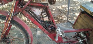
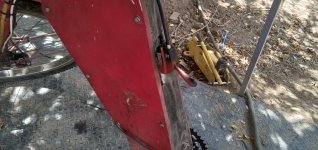
By the time I reached work, I thought there was steam coming off the headlight but it was actually wisps of smoke from wiring inside the "triangle" where all the interconnections, relays, etc are at. I yanked the battery disconnects (main and lighting), and opened the side panel of the triangle, and found no smoke or obvious wire damage. Then I had to work my shift, and try to do some troubleshooting in the breakroom; spent about an hour but it's too dark in there and I had no multimeter with me, and I was completely exhausted, so I couldn't do much and couldn't locate the problem, so I rode home without lighting battery connected while it was still light enough outside to not need them as much.

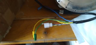
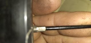
Once home, after satisfying Jelly's need for play and greetings (after which she always just goes to schmoo somewhere), and sitting to eat something and rest for an hour, I went out to troubleshoot the problem. First I found that the wires to the little switch on the bars had heated enough to somewhat melt the insulation on them together (there are three paralleled tiny wires to provide 12v up to the switch, they were all stuck together along their length). They had not damaged any other wires in the big cable they're in, but I decided to do what I should've done before which is to run a separate power wire from there to the switch...though I haven't actually done that yet (for now it is just using a spare set of wires in that cable). There just wasn't time to do more than getting the basics working before I had to try sleeping (very poorly) to be able to work the next day.


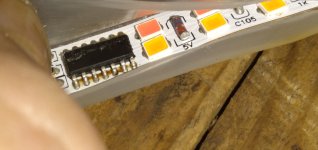
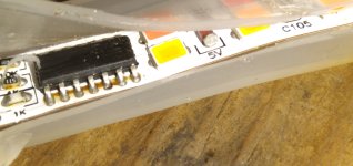
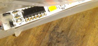
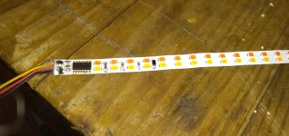
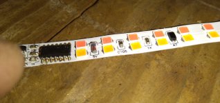
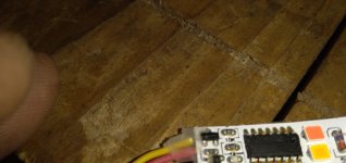
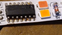
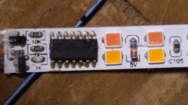
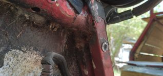
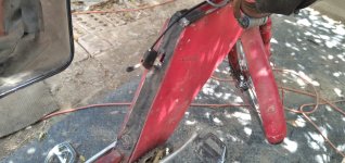
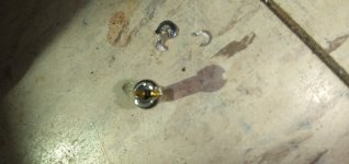
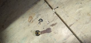
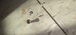
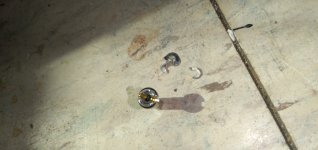
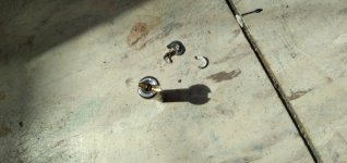
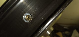
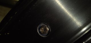
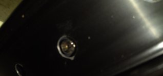
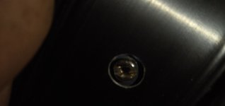
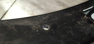
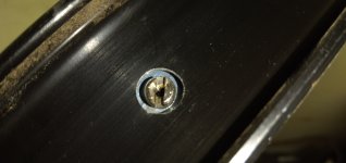
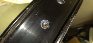
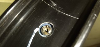
Anyway, after going thru all the wiring, I eventually found the source of the whole problem--one of the side marker light strips, on the left side of the edge of the cargo seatbox, lost it's wiring and that wiring shorted lighting positive to lighting ground.

"lost it's wiring" means that something caught the wire and ripped it off the light strip, and out of the hole in the wood next to it that the wire comes out of. The wire was ziptied along the bottom of the trike frame pretty closely, so whatever it was would've had to be large or curved, or a branch...and since I didn't see (or feel) anything like that, it must've been in one of the numerous stretches of inches-deep water in the roads on my commute path. None of them came all the way up to the trike bottom, which is something like 10" off the ground, but some were pretty close.

I ended up just tying that off and taping off the ends, until I have time to reconnect it to the light strip. Just for safety of the signal wires to the rear, I disconnected the power and ground for the lighting from the multiwire cabling going back there, and ran separate new thicker-gauge wires to power the rear tail, down, brake, signals. The actual turn and brake signal wires are still in the multiwire cable; that's too complex to change out in the three hours or so I had to work on it, since it goes up thru all the handlebar wiring and stuff--the power/ground only go to the distribution bus inside the "triangle", so much easier and quicker, and something I could still (barely) do in my exhaustion.

Once it was all working, I ziptied it all down while it was running, so I could see if I messed anything up right away, then shut it off and went inside to collapse for the night.


Now, I didn't touch any of the wiring for anything other than the lighting...but there is now a change in behavior for the PAS (cadence sensor only) at speeds below around 11-12MPH during acceleration (but not during deceleration, only while the system is under load)...it surges repeatedly, at about 1/2 second-ish intervals, with what feels like complete loss of power between the surges. Throttle under the same circumstances works perfectly. Above that speed, PAS works just fine.

The problem does not track the speed of my pedalling--I can be in a gear that virtually freewheels the cranks and spin as fast as I can physically do so, and the surging happens exactly the same, and does not follow the crank RPM, it appears to be only at that fixed rate.

So it can't be a problem with the sensor itself (which is the cadence part of a TDCM BB torque sensor; I'm not using the torque part ATM).

I haven't changed any CA settings, or even accessed the setup, in quite a long time, so unless moisture from the rain got into the CA and caused it to corrupt a setting, there shouldn't be anything there to cause this. I can't see anything unusual about the throttle output voltage reading on the CA diag screen, in either PAS or throttle control.

It can't be a controller problem, since the throttle signal fed to each of them comes from the CA output, and that obviously works perfectly fine using the throttle input to the CA.


After I do some other critical housework (fence repairs primarily) this "weekend" (sun/mon) I will use my analog multimeter to watch the throttle output from the CA to see how it is changing during PAS use. (vs throttle)

Then if it verifies that the CA is sending a different throttle signal under PAS than throttle (even though they look the same on the CA diag screen), I will go thru the CA settings to see if something changed there, somehow.

If nothing changed, I'll have to check out the PAS sensor / wiring, which do go thru the triangle box with the lighting wiring (but are tied down separately and weren't handled during the repairs), in case something was somehow damaged.

If I don't get to do it this weekend, I will be off work for the week after next, and will do it then (if nothing else comes up that's higher priority, which has happened frequently of late, and taken up all the time/energy I have.

Hopefully I'll also have time that week to do the stuff previously posted, to get the GMAC on the left side...but at this point I am not expecting to accomplish much, given the way things have been happening lately.


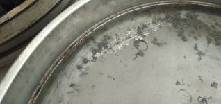
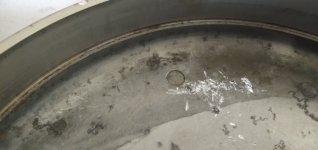
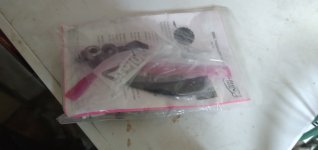
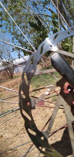
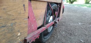
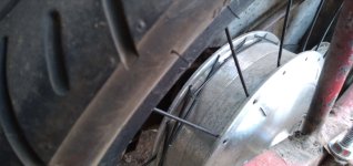
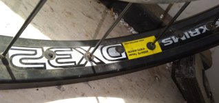
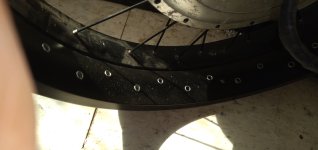
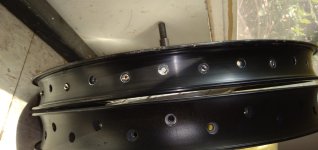
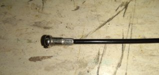
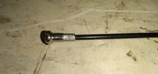
For instance, last week (saturday?) on the way home from work I had a flat, virtually as I reached my driveway. The hole turned ot to be on the sidewall of the tube, but there is no corresponding hole in the tire sidewall. The tire did have bits of thorn embedded in it here and there, only in the tread area, but none of them went thru the whole tire thickness, much less thru the double-cut-up-innertubes used as tire liners (which also don't have any part of them corresponding to the hole in the tube). The hole is more like a tiny slice in shape, but there's no marks around it, and you can only even see it when it's inflated and leaking (rapidly).

I just marked the spot and replaced the tube with a new one, so I can patch the damaged tube to keep as a spare.

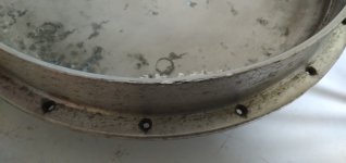
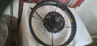
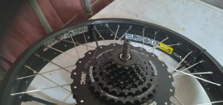
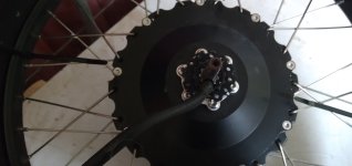
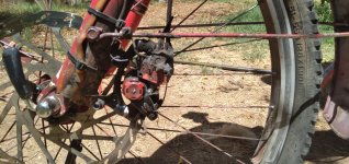
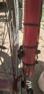
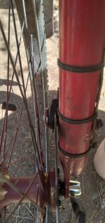
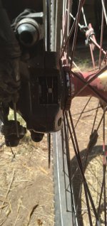
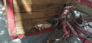
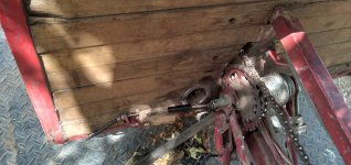
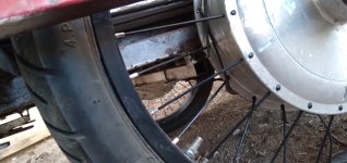
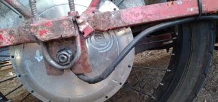
While I was working on it, I also took some pics of the axle and dropouts (will post them later); there's zero twisting of the axle in the dropout, it still fits so tightly I have to use the rim/tire to lever the wheel out of them, and have to use a prybar to lightly spread the inboard dropout enough to get the axle back in that one. So the dropout clamps are working. :)


Other stuff to fix around the house also keeps accumulating, too. :/
 
Is it possible that you have a bad ground and that the controller or CA is creating noise that due to said bad ground is interfering with the signals going to/from the torque sensor and causing intermittent operation?
 
I suppose it's possible.

FWIW, the problem went away a couple of days after I posted last, and has not returned. I suspect water intrusion into the sensor / BB itself that dried out in the intervening time, as I have not yet had the chance to open anything up and check on it, so I haven't touched any of the connections yet, or investigated any of the settings.
 
Hoping to start building new wider dropouts (well, really just moving the outboard dropout out a little, as the inboard one is pretty well "locked" where it has to be by the placement of the pedal-drivetrain transfer-axle output gear) on the left side to hold this Grin-laced GMAC motor, maybe tomorrow, if everything goes as it should for other household maintenance stuff that must get done first. It'll be run by the old Grinfineon already on that side that's presently running an MXUS 450x.

Rest is pics of the other stuff I bought from chuyskywalker's "garage sale" thread, a couple of old Ultramotors (one broken when he opened it up, damaged a bit further in shipping, mostly to be used for spare parts for the others, or maybe fix it up for a middrive usage since the spoke flange is broken), a spare rim that matches another I already have an Ultramotor (well, did until the spokes all failed at the same instant for as-yet-undetermined reasons).
 

Attachments

  • 20221218_114851.jpg
    20221218_114851.jpg
    2 MB · Views: 64
  • 20221218_114900.jpg
    20221218_114900.jpg
    4 MB · Views: 64
  • 20221218_114905.jpg
    20221218_114905.jpg
    2 MB · Views: 64
  • 20221218_114916.jpg
    20221218_114916.jpg
    2 MB · Views: 64
  • 20221218_114930.jpg
    20221218_114930.jpg
    2 MB · Views: 64
  • 20221218_114936.jpg
    20221218_114936.jpg
    2 MB · Views: 64
  • 20221218_114948.jpg
    20221218_114948.jpg
    2 MB · Views: 65
  • 20221218_115214.jpg
    20221218_115214.jpg
    2 MB · Views: 65
  • 20221218_115221.jpg
    20221218_115221.jpg
    2 MB · Views: 64
  • 20221218_115235.jpg
    20221218_115235.jpg
    2 MB · Views: 63
  • 20221218_115247.jpg
    20221218_115247.jpg
    2 MB · Views: 63
  • 20221218_115301.jpg
    20221218_115301.jpg
    2 MB · Views: 63
  • 20221218_115311.jpg
    20221218_115311.jpg
    2 MB · Views: 63
  • 20221218_115333.jpg
    20221218_115333.jpg
    2 MB · Views: 63
  • 20221218_115408.jpg
    20221218_115408.jpg
    2 MB · Views: 63
I did not get to the dropouts project yet...it has taken me until today to get the new Schmoo Space finished (well, actually today). More on that in the Beginning of a New Life thread.

I was going to install the 12V Meanwell from here:

as a built-in charger for the lighting pack, but I had forgotten that it only goes up to 13.8v, which is enough to run the lights/etc., but is not enough to charge the lighting battery (which is a 4s2p EIG NMC pack, that I charge to 16V). It *would* work, since I rarely use more than a few Ah of the 40Ah pack before it gets recharged, and it would, with the MW in place, get recharged nearly every day when I plug in the trike to charge the traction pack (as both would be wired to come on whenever plugged in), so the pack would even with the greatly reduced capacity of only charging to 13.8v be able to do the job I usually need it to...I just don't like running out of lighting power, whcih is why it's a 40Ah pack. ;)

The Satiator I usually use to charge the lighting pack with could be mounted to the trike, but I use it for other things sometimes, and it'd be annoying to have to get it off the trike to do that. So for now, I'll just keep doing things the way I have, until I run across a MW real cheap (like the 12V one was), that will go up to at least 15v.


I did get a couple other things on the trike done. The left taillight at the bottom left corner of the back of the trike was knocked off trying to load up the stuff at Lowes for the Schmoo Space last Sunday;
20230115_145247.jpg

these lights are only glued on with silicone because they don't have any mounting points for screws, etc,
20230115_145408.jpg
and at the time I didn't want to drill thru them and risk damaging the PCB inside. However, I checked the ohter lights and three of them were loosening, and could be knocked off by the wrong bump on them or a sufficient shock to the trike, so I decided it was time to screw them on anyway.

I didn't have the right length screws, just too long or too short, to go thru the wood from behind them and *just* into the plastic, but not far enough thru the plastic to break anything inside. So I ended up using a stack of washers on each screw head (drywall 1-1/4", as these were the best fit that might keep grip on the plastic, of what I had), to keep them from penetrating too far in the lights. Two per light, one top and one bottom, seem to be enough to hold them on pretty well. I did not remove any of the lights, leaving any glue that is still good on the other five intact while scrwing them down, though I did not reglue the one that had already come off, just screwed it down.


The other thing I fixed is the right hand tail/turn strip on the top rail of the trike, over the cargopod deck. I don't know when it failed, but I noticed it after fixing the wiring issues a few posts back. Basically the way these work is there is a little MCU in each strip that when they are powered on first "cylon" the red lights, then go from dimmest to brightest over a second or so, and stop there. When the turn signal wire is engaged, the red lights go out and the yellow lights are strobed a few at a time from the MCU end to the other end, to make a directional movement of light. The MCU end goes at the center of whatever vehicle, bike, etc that these are used on, so the signal goes outward in the direction of indicated turn.

This one, however, doesnt' go past the power on stage where it starts with all LEDs dim except the one bright group of them it starts out with in the middle that would t hen move to one end and back to the other (cylonning, if you've ever seen either BSG version).

The turn signal doesn't work either, because the MCU never proceeds past the very first poweron step.

The LEDs probably all still work fine, so if I could get a chip to replace this one I could fix the strip. Something like a Nano might be able to drive it, or ATTiny or something, but that requires software I don't yet know how to write. The strips are so cheap ($20 a pair when I got them, now about half that like these
https://www.ebay.com/itm/402628880576
that it's not worth spending more than a couple bucks fixing them, especially if it takes any serious time to do it...though I hate wasting things.

Thankfully, I already had a spare set of them, bought to build into the still-waiting-for-time Cloudwalker Cargo Bike. So I took one of those and replaced this one with it, so now both top rail tail and signal are working. I still did not get to doing the brake light switching for those strips; there's something specific I have to build for that that I cannot ATM remember, but it is more complicated than just connecting it to a brake switch. :/

I never got to it originally because Kirin's final problems started literally as I was installing these a couple of years ago, and within the month she'd died, and not long after so did Yogi, and my world basically ended again like it had at the start of the BoaNL thread. So I never got back to doing any of that (or the CCB bike project, which was also about to start at the time).

Anyway, the trike is now functional for me to go back to work Tuesday....
 

Attachments

  • 20230115_163744.jpg
    20230115_163744.jpg
    2.2 MB · Views: 34
  • 20230115_163810.jpg
    20230115_163810.jpg
    2.1 MB · Views: 34
  • 20230115_163815.jpg
    20230115_163815.jpg
    2.4 MB · Views: 34
  • 20230115_164108.jpg
    20230115_164108.jpg
    3.5 MB · Views: 34
  • 20230115_164113.jpg
    20230115_164113.jpg
    2.8 MB · Views: 34
  • 20230115_164117.jpg
    20230115_164117.jpg
    2.9 MB · Views: 34
  • IMG_20230115_164155.jpg
    IMG_20230115_164155.jpg
    2.2 MB · Views: 34
  • IMG_20230115_164218.jpg
    IMG_20230115_164218.jpg
    2.2 MB · Views: 34
  • IMG_20230115_164225.jpg
    IMG_20230115_164225.jpg
    2.1 MB · Views: 34
  • IMG_20230115_164233.jpg
    IMG_20230115_164233.jpg
    2.2 MB · Views: 34
Over the last many weeks have done a lot of cleanup and reorganization to be able to use the backroom workstations again (which I kind of abandoned during the last couple of years or more of bad stuff that has been happening), so I can restart and continue various projects, hopefully including the Lebowski controllers. I still have a ways to go before I can do that, but I'm mostly there.

In the meantime, I had a couple of things requiring repair on the trike the last week:

After the heavy rain and flooded roads the brake has been less and less grabby. I've readjusted the cable tension at the lever, but it didn't really help...eventually as I was checking the pads for contamination (like car oil splashed on them from the road when it was flooded) which I didn't find, I remembered that with the disc brakes, the cable tension isn't really sufficient to readjust the pads (unlike with rim brakes), and the pads actually need to be adjusted. (this has to be done so infrequently I tend to forget).

Fixed that in a few minutes, but while doing all this also found the rotor bolts were *all* loose, most of them so much that the thicker solid part of the bolt between heads and thread that sits in the rotor hole was fully outside the rotor. This was allowing the rotor to rock (or rather, the wheel to rock while rotor was locked in the calipers) and has been making me think that there was a headset bearing problem, or other issue. Just to make it simple I swapped the bolts out with new ones that came with the Avid rotor/caliper kits I'd gotten originally, that still have their loctite on them, and this fixed that problem.


A few days later, as I was pulling into the driveway and grabbing my big blue recycling container to pull it along with me, where I often use the throttle to control hte motor since where I stop to grab the handle of the container makes it very hard to start with the pedals...letting go of throttle didn't stop the motor completely and had to use the brakes, which pretty much never happens.

Letting go of brakes started the motor again, so I held the brake and found the throttle lever physically stuck on just a tiny bit past the deadzone. :(

Now, the throttle cable from the ATV style htumb throttle control to the cable-operated thorttle hall unit is where one of the zipties holding the top end of the "bush guards" that keep cold (or hot) air off my hands, and hold the sequential turn signals and DRLs....I had to move that around a lot in adjusting the brakes at the handlebars the previous weeks, and then moved it way out of the way to adjust it all back to zero when fixing them the right way, which moved the throttle cable around enough to cause whatever this is.

It's definitely sticking right at the exit of the throttle control, but I couldn't find the spot actually causing it. I ended up oiling the cable, and working the throttle a lot full range with power off (which I tried before oiling it to no avail), and this seems to have fixed it.

Just in case, I adjusted the thorttle in value in the CA so the zero end is now a tenth of a volt higher (from 0.9 to 1.0v) so that if it *does* stick again in a traffic or other situation it won't be likely to cause a problem.
 
This past week, I had essentially this kind of pad failure on the SB Cruiser (but it's fork is sturdy and had no problems; instead the pad itself just ripped a chunk off and I lost about a third of my braking power, still leaving more than enough to lock up the front wheel with the Avid BB7 MTN calipers with 200mm rotor).

The cause of mine was the spring clip that pushes the pads apart / holds them against the calipers when not being used somehow touched the rotor, and bent and was welded to the rotor (probably all during that specific braking event).

This was at an otherwise unoccupied intersection on my way to work, so I pulled up onto the sidewalk there and checked the brake, not knowing the actual problem/cause, but concerned over the sudden change in braking power and the ticking noise (once per rotation). I didn't see the problem at that moment, and needed to get to work, and it was over 100F already out there, so I chose to reduce speed from 20MPH max to 15MPH max and continue the mile or so left to work, and coast down early to stops and use the regen braking to finalize them, avoiding use of the unknown-fault brake rather than relying on it, just using it to hold the trike stopped while at the traffic lights.

After my shift ended, I was able to examine the brake in detail in the coolness of the breakroom where I park the trike, and found the springclip piece welded to the rotor. I should have taken a picture of it before touching it, but I rubbed my fingernail across it and it came off, and I could not find it on the speckled tile floor. :( I thought I got pics of the rotor pads and rotor, but apparently did not so I'll have to go take some and edit them in here tomorrow.

Because I do only have the front brake, I carry a spare set of pads and spring clip with me; they're the "meh" Dymoece pads
rather than the Avid originals (which is what were damaged), but they work almost as well, and are more than sufficient, even though they wear faster (and aren't copper backings like the Avid so presumably don't shed heat as well, which might be why they wear faster?).

It's only a minute to swap them out, and a few minutes adjusting the caliper pad knobs and brake lever cable adjuster, then it takes a couple dozen to a few dozen miles to wear in the new pads for best braking (they're about halfway into that process, I'd guess, but they're sufficient as-is).


I just don't know what caused the spring failure that allowed it to touch the rotor; it shouldn't be possible; the pads were still only about half worn thru. Maybe the pics of the remainder of the spring or the pads will help figure that out.


(this is crossposted to a brake failure thread over here:
Mechanical Disc Brake Lockup )
 
If one of the pads self-welded to the rotor, it is possible that excessive heat conducted through all parts of the caliper, including the spring, causing it to fail. The rotor itself along with the caliper may have absorbed too much of the kinetic energy become heat while stopping.

Your rig is quite heavy, and I'd think that Avid BB7s are insufficient for the job.
 
Well, it certainly gets hot--it isn't glowing even after a hard stop from 15-20MPH with a few hundred pounds of cargo :lol: but it'll blue the rotor surface under those conditions. (that doesn't happen under normal use, but the rotor will still be too hot to touch after a stop.)

The brakes themselves are sufficient to lock up the wheel and skid, so "better" ones wouldn't provide any better braking, if that's what you mean by "insufficient"?

As for heating the spring...I see a probable color change at the edges here and there, but I don't know if that is from the manufacuring process or brake heating. (probably the latter)

What's left of it still feels just as springy as an intact spring from another pad set, to my fingers, though I don't have any instrument for measuring the force required.

The pads certain get hot, you can clearly see the color change of the copper.

The gouged and broken pad is the outboard side, the carved but otherwise intact pad is the inboard side; I can't find anything on the rotor that would have carved that line in it; it's smooth on that side, so it must have been something that stuck to the rotor or was in one of the rotor holes, and came off later.

The spot on the rotor where the spring bit welded is on the ~ 10oclock position in the outboard side pic of the rotor; you can see the scar leading up to the point it was stuck on, at the top/right of the scar closest to the fork.

I can only attach 10 pics to this post, so the rest are in the next.
 

Attachments

  • 20230807_123425.jpg
    20230807_123425.jpg
    352.6 KB · Views: 5
  • 20230807_123431.jpg
    20230807_123431.jpg
    1.5 MB · Views: 4
  • 20230807_123433.jpg
    20230807_123433.jpg
    514.6 KB · Views: 3
  • 20230807_123436.jpg
    20230807_123436.jpg
    797 KB · Views: 3
  • 20230807_123649.jpg
    20230807_123649.jpg
    916.3 KB · Views: 3
  • 20230807_123720.jpg
    20230807_123720.jpg
    4 MB · Views: 2
  • 20230807_123733.jpg
    20230807_123733.jpg
    1.1 MB · Views: 2
  • 20230807_123740.jpg
    20230807_123740.jpg
    1.1 MB · Views: 2
  • 20230807_123755.jpg
    20230807_123755.jpg
    897.7 KB · Views: 3
  • 20230807_123834.jpg
    20230807_123834.jpg
    2 MB · Views: 5
Last edited:
Back
Top