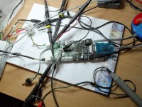
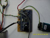
Timing Adjustment Tool

RE Running at of processor speed in PIC18.

What clock frequency are you running.

Are you coding it in MPLAB with Assembly or C?
Or something like STAMP basic?

A 40MHz internal PIC18 is pretty quick.
10 Million instructions per sec if the PIC18 is 1/4 fclk.
 
Hi 7circle,

It is currently clocked at 20Mhz and written in C.
I think with a bit more work it will be ok doing the timing prediction and shifting, if I keep the interupt routines tight enough.

The bit I am doubtful about is whether I will be able to send data about RPM and phase angles back to the computer while it is operating.
The original goal was to have 1 e degree resolution with a motor spinning at 70,000 e rpm

Being essentialy just an 8bit processor, some of the mathematical operations, like division, can take a significant amount of time.

I will get back to looking at this project properly sometime in the autumn when the weather turns bad, but for the moment it is e riding season, not computing season :)

Burtie.
 
Burtie,

Just a thought - have a look at field weakening and vector control, the timing advance if done at the proper time will actually allow you to acheive higher top end speed than the raw kV of the motor would suggest by weakening the phase field it's about to oppose enough to cancel it out and then firing at an advance dependent on the motor but detectible based on phase current and RPM and known natural KV.

It has an added benefit when applied lower in the RPM band (vector control) of maximizing torque and reducing noise to next to nothing (ie: harmonics).

It's late I may have mispoke but the relevant tech is findable with the keywords - hope it help!

-Mike
 
fine work burtie,
you may not have any idea how badly we need this, for a start theres everyone who want a colossus to work properly etc etc.
myself and splinteroz have been doing battle in the shed and agian hit the timing is out brick wall -a wall that i am fairly familiar with now..

we ideally would want to adjust timing on the fly to find lowest amps at maby just 3 rpm pionts, then program that in.
if theres anything we could do to help you along?
knowing that we are just waiting for some rain in england is reasuring though. :lol:
 
Hi toolman2,

Thanks for the encouragement
Your prayers for rain in England are beginning to work :mrgreen:

I will dig this project out from the bottom of the pile soon and get it up to speed again.

The plan is to get it working in some basic form first, target it initialy at a currently available PIC18 prototyping board, so that we can just buy the electronic hardware off the shelf.
This may not give us the neatest/cheapest/best optimised platform, but it should be available quicky and easily to give us some units for testing :D.

When I have something working, I can let you guys have the software executables or perhaps a complete prototype and you can help test it out?

I will keep you posted.

@Mike, I was hoping to keep it simple to start with!
Maybe I can add the field weakening and vector control bit in the next phase :wink:

Burtie
 
good to hear burtie,

yep i think keeping it simple would be the best way to start, it seems like 0 timing is a good place to be for motor startup in either direction, and can be achieved by halls in the middle of stator gaps easily.
from there just two rpm points at which timing can be advanced (or retarded??) would be awesome. (one could then be to fix timing for a star to delta change)

i dont know much about this digital stuff, but just useing one hall (once up and running from the 3) as a reference and the chip spits out 3 (120deg apart) avoids the variation of each sensor placement (matters more at high rpm) and maby this is easier?

so many times here ive seen massive amounts of enthusiasm/excitement, then the complexity builds and it becomes too big a project and we often lose that basic but very functional item or result.
so we really appreciate your efforts and 2 of us here in oz are keen to pay for and test, and help in any way.
 
Its getting wetter!
I have done a bit of work on the project by changing the hardware to a more suitable prototyping board.

I have removed or disabled all the fancy features in an attempt to buy processing power to allow the basic functions to work well.

It does sort-of work, but still has some problems which render it unusable as a decent tool. I will continue to follow my current thread for a while to see if I can fix it.

If I cannot get it to work using a reference from only one hall sensor, I could simplify the design further by just taking the signals from all three hall sensors and applying a delay to each. This has a disadvantage, it would mean that the relative positions of the sensors would then need to be pretty accurate.

Good news :D :
I now have a compiler and prototyping board for the much newer and more powerful PIC32 devices, at some point soon I will port my firmware on to this and hopefully a lot of the problems will then go away :) , ---but, there is a bit of a workup to do this :?

Burtie.
 
Burtie,

I'd not been following this thread, but during a discussion on the "fitting Halls to an Astro" thread I happened to mention that there was an option to switch between sensored and sensorless operation and vary the timing. Here's what I wrote on that thread:

"the idea would be to run in fixed timing sensored mode up to a reasonable rpm, to give good start up and low speed torque, then switch to sensorless mode for medium to high speed running. The Halls will give the solid position feedback needed for start up at low speeds, and by switching to sensorless you get the ability to do timing adjustment on the fly, just by varying the threshold at which the zero crossing detectors operate. This is similar to the way that pre-digital electronic ignition systems managed to get advance; they used a sinusoidal sensor and varied the threshold on a comparator with rpm."

It has occurred to me that this might be a useful approach for your timing adjustment tool. Use the microcontroller to generate the variable comparator threshold, so varying the timing. The output of the comparators could be used as pseudo-Hall signals.

It would work because the BEMF waveform has a slope on it around the zero crossing point (it tends to look trapezoidal). Shifting the voltage at which the comparators detect the zero crossing point moves the switching point up or down, which retards or advances the timing.

You could even make the thing independent of the motor back EMF by using a linear Hall sensor system to derive the signals, maybe.

I've not idea if it would work effectively, but as it's essentially the same system that sensorless controllers use I can't see any good reason why it shouldn't.

Jeremy
 
I have seen RC controllers that have a sensorless fallback mode. The Idea being that if a hall failed the plane could "limp" home.

I was thinking the same that a controller that went into sensorless mode after say 1000 or 2000 rpm would be able to run up to high revs on the larger outrunners.

Not sure if you want your circuit in on the power phases. I can't imagine including a sensorless controller logic circuit into a sensored controller.

Anyone game!
 
Jeremy,

I really like that idea. I've been sort of following this topic too. I know how I would do variable timing, with a phase locked loop, but it is either a lot of hardware in analogue or a lot of programming in digital, so I was just standing back for now.

But your idea might be a neat way of doing it in analogue.

Nick
 
Jeremy Harris said:
Burtie,

they used a sinusoidal sensor and varied the threshold on a comparator with rpm."[/i]

It has occurred to me that this might be a useful approach for your timing adjustment tool. Use the microcontroller to generate the variable comparator threshold, so varying the timing. The output of the comparators could be used as pseudo-Hall signals.

Jeremy

Hi Jeremy,
Sounds like an excellent idea, I guess that probably would work.
The small drawback would be the need for extra hadware for analogue comparators and perhaps connections into the phase leads.
I wish I had a bit more time to play with all this stuff! Give it a try someone :wink:


I had a minor breakthrough with the original digital design this evening. I now have all the micro-controller interupts behaving properly at last for the capture, compare, timer, and pin state change events (sometimes all at once :shock: ). Hopefully should make some good progress now :D


With my Turnigy 80-100 test motor on the bench here, I can now apply a variable combination of dynamic(rpm dependent) and static timing advance.
It is amazing how much I can raise the Kv of this motor by using just the right amount of advance at the right time :mrgreen:
 
Come on Burtie,, you really need to get a handle on this :p ,, my retro gear box is very nearly up and running ready for testing and this little tool will make the whole setup the bees knees :wink: .
Its great that you are still looking into this and I hope it pays off. Now the dark nights ( and shity weather is coming ) Im gonna have to find a nice electronic project to get my teeth into before the wife decides that the house need re-decorating :mrgreen:
 
Too late for me, I'm three quarters of the way through fitting a new kitchen. I had a few days respite waiting for the new sink and tap to arrive, but they came yesterday afternoon so it's back to it today. After that, SWMBO has ideas on remodelling the bathroom, too...............

Back on topic. If you wanted to try a real Heath Robinson analogue approach you could look at adapting one of Keywin's sensorless boards (I have a couple lying around here somewhere if you need one). These have a bunch of comparators used as zero crossing detectors and I'm sure it should be possible to add a pot to shift the comparator zero detect point up and down. This would give a crude way of adjusting timing both towards advanced and retarded.

As I mentioned previously, you could add a three pole changeover switch to select either neutrally timed Hall sensors (for start up) or sensorless mode.

It's nowhere near as elegant as a proper digital approach, but it worked well enough to provide ignition advance on a lot of early cars with electronic ignition.

Jeremy
 
Thanks Jeremy for the kind offer of the use of the analogue sensorless adaptor. I will bear it i mind if my current idea does not look like it will provide the desired results.

For the moment I feel I need to concentrate on developing the digital design that I have started.
I seems to work fairly well on my test bench here at home, but I need half a ton of equipment (computer, PIC programmer, logic analyser and oscilloscope) to make it perform, diagnose and configure it.

The challenge for me at the moment is to try and distill the unit into something that :

Will work reliably on its own,
I can replicate at a reasonable cost,
Is simple to install, configure and operate,
Will operate with more than one motor configuration (currently just designed around 14 pole motors)
I can put in a jiffy bag and post to the other side of the world,
Can be remoteley re-programed without the need for specialist expensive equipment,

Maybe its called production engineering, I dont know. What I do know is that it will likely take a bit of time.

But there is no better time to do it, the shity weather is-a-coming..... :D

Burtie
 
A quick update to prove that I haven't really been sitting on my arse doing nothing for ages :wink:

Now using a new PIC18 prototyping board that may be actually small enough to mount somewhere on a bike one day.

Timing Adjuster Prototype 2.jpg

Here is a short demo showing how advancing the timing of a neutrally timed motor can affect its no-load speed.

Bottom trace shows signal from one of the hall sensors in the motor.
Top trace shows the corresponding signal synthesized by the timing adjuster.

http://www.youtube.com/watch?v=CGsLMY6XuDg
[youtube]CGsLMY6XuDg[/youtube]


I wonder if this could be enough turn my 40mph bike into a 50mph one?


EDIT: looking carefully at the 'scope traces, I estimate about a 13% increase in no-load speed in this demo, using 20 degrees of advance WOT @ 24volts.


Burtie
 
excellent work burtie,
im glad your honest and clear about the amount of work/time required to get this "on vehicle".
and i like how you keep chipping away at it.
 
Kudos to you Burtie, marvelous work. :idea: :!:

Can you put me down for one or two from the first batch? I'll pay now if it helps, do you have a paypal?

I wish I could offer some tech, but you seem to have sorted it out yourself.

Long live the overclockers of this world.
 
Much respect Burtie!

I always enjoy your videos, and when your videos are showing the ultra-kick-ass benefits of timing controller, it's that much easier to love them. :)
 
Thanks for the positive comments guys :)
I am not quite in a position to start taking orders for these thing yet, -but we are getting there.

Have ported the firmware, (with some amount of pain) to newer hardware that runs at twice the speed = twice the processing power.

About to send some prototye units to one or two members here who have kindly offered to help me out with some beta testing, esp using the larger motors with 12 pole-pairs.

SDC12045.jpg


Here is a bit of video showing some no-load testing of the TA on my Turnigy 80-100 equipped Stinky.

http://www.youtube.com/watch?v=FTO14L1OLOg
[youtube]FTO14L1OLOg[/youtube]

:D
Burtie
 
Way to go Burtie,,,
I wish I was running a larger motor I would love to give this a wizz on my bike. This will be a very good solution to use with the reverse GB I have put together.. Keep at it mate. 8)
 
Cool... Cool... very cool.

I have a colossus 10 pole pair motor (I think it is 10 pole pair) that I am working with toolman2 on, he has an ocilliscope I have a background in electronics (a bit rusty tho').

I want/need one of these earlier the better, as we have measured that the lack of advance is killing the top end of the motor.
 
good job man!!! I don't know nothing about what every body talk here but this will be great if your tool will work on 9c wheel and 18 fets controller
 
Back
Top