Ultracap Bike

Wow, what a day. I got to (for the first time) do what many folks here already take for granted, ride an electric bike out on the road. I've shown the results of a few tests using the various components already, so the next challenge was to make the bike mobile, to unplug it. I needed first to come up with a way to support the large ultracap module behind the rear seat, and fix all of the required devices and controls into place. I scrounged around, and with the help of some friends in the Physics building I found some aluminum sheet and brackets that had been used to hold window air conditioners into place. After cutting, drilling, and bolting things into place, this is what it all looked like:

test_drive_setup.jpg


Some details from the side and rear of the support rack:

rear_rack_side.jpg


rear_rack_back.jpg


rear_rack_under1.jpg


rear_rack_under2.jpg


You'll quickly note that there is a black controller box that is duct taped to the top of the capacitor housing. That's the controller that came with the NineContinent Kit, which is "pedal first" and has a 20 A current limit. I'm using it until the cable I need for my Kelly controller shows up, so for now only 20 A is allowed, and no regen is possible.

I wanted to do a street test to see what kind of acceleration, top speed, and power/current draw there would be, so I set up the charging station to get the module to 48 V and monitored it with the Cycle Analyst.

charging_station.jpg


Soon I was ready to take a cruise on College Street.

[youtube]KW8PF5RiRnI[/youtube]

With the throttle maxed out, it pulled the expected 20 A, and power draws ranged from 700-750 W. I think it's a 500 W rated motor. I also went up a very steep hill (probably about 10% grade) at a good speed while pedaling just a little bit along with the motor. In all, a lot of fun!

The next step will be simple (unloaded) regen tests in the lab, using the Kelly controller with a proportionally controlled twist brake on the left handlebar.
 
Remarkable, all the way. If only the range/weight/capacity could someday equal that of batteries.

It's very inspiring to see work like this brought forward against all naysayers. So, if it has but a two or three mile range....
it's not got any battery! Neat! :p
 
Well done! Now report the max range you can get on a flat ride at a given speed. Just a minor thought: the back of that mounting plate is crying out for a "bumper" with red lights mounted in it, for example some of Justin's new ones here: http://www.ebikes.ca/store/store_accessories.php (about 3/4 down the page).
Soon, you'll add some LiFePO4? :wink:
 
mount your ultracaps in a bob trailer on back, you have a total of 3? the bob trailer has the high rails around the side and that will keep them from hitting the ground or obstacle in event of falling. by putting them back down there, it keeps the center of gravity low also, much better than piling them all on the rear rack, and you can carry a big battery pack there too. looking good. is this a one semester project?
 
Thanks for the kind sentiments, Reid and Paul. This has been a lot of fun for us so far and I haven't even "regened" a single amp yet. Looking forward to doing some rewiring soon, involving the Kelly controller. At least I think I know what wire to connect where...

Dennis, combining your trailer idea with Paul's battery primary supply is (I believe) one of the most interesting longer-term approaches to this bike. For example, with the three 48 V modules (I have 3 big ones at 48 V and three small ones at 16 V), I could connect all three of them in parallel with each other AND a 48 V battery... with a current limiter on the battery terminals you can make sure it never sees a huge current draw on its own, even when it's just charging caps. You could do the job with one 48 V cap and one 48 V battery too, probably just as well, but it sure sounds fun to carry around that much charge.

As for the immediate plans, I'll be working on the rear rack this week until the cable for the Kelly controller shows up, I want two more braces at the very rear end and will start figuring out how to cover the whole thing.
 
How long does it take to charge up?
How far will it go on a charge?
 
E=IR said:
How long does it take to charge up?
How far will it go on a charge?

Charging is quite fast. Although I have to limit my charging current to around 15 A (the variac starts to hum angrily at me if I try to go faster, and I've long since blown its fuse and replaced it with a sturdy 1/4" diameter stainless steel tubing stub :) ), I am charged to 48 V from dead (0 V) in under nine minutes. If the variac could handle twice the current, I'd be done in around 4 minutes.

As for range, I would really like to directly test this... but there's a lack of uninterrupted flat roads here in the city! At the moment I'm doing all the wiring for the Kelly controller, but I can make a (probably poor) estimate.

Let's say that the motor wants an average of 20 A of current while the pack discharges from 48 to around 24 V. I could theoretically go down to 18 V before the Kelly went into an undervoltage error, but no sense in pushing it (and the return on investment in terms of energy is not great at low voltages). Let's also say that this corresponds to an average speed of 24 kph (15 mph). Hope I don't make a dumb mistake here.

i = C dV/dt, so dt = C dV/i = (160 F)(24 V)/(20 A) = 192 s = 0.05 h
0.05 h * 24 kph = 1.2 km = 0.75 miles

Hence the use for acceleration/deceleration only, while using the pedals at high speeds to cruise, or more hopefully, to achieve through-the-road regeneration.
 
Update time... I received my control cable (J2, 14-pin connector) from Kelly on Friday and spent most of the work day Monday wiring things up and making a mess. I mounted the Kelly to the top of the capacitor module; I couldn't resist since the module had frame screws with exactly the right spacings. Here's everything wired up (most of the mess is hidden behind the module):

rear_with_kelly.jpg


I generally swiped a bunch of wires and connectors to get it together. All of the controls are mounted on the handlebars (sloppily):

handlebars.jpg


Red circle: Twist brake for proportional braking control.
Orange circle: Brake switch button. This is a hack job in terms of mounting, but it is extremely convenient - it's push to close the circuit, and it opens again when you remove your thumb. No need to flip the brake on and off, and you can easily twist the handle while keeping your thumb in place. Anyway, I liked it.
Yellow circle: Cycle Analyst. I rewired it for the Kelly with a the cap as power supply and to the speed sensor on the front fork. I don't have my high current shunt resistor so it can't track amps or power use yet. It's on the way.
Green circle: Thumb throttle. It's a 1-4 V output type, which called for some fancy reprogramming inside the Kelly's software to make it look like a 0-5 V type. It's used without a switch.

I was still able to go for a spin and get some rough data involving voltage swings... took some trail runs on a mostly flat stretch and went up and down a steep hill. Here's what I found:

1) 0.33 km run on mostly flat street, motor only (no pedal assist), average speed of 10 km/h, capacitor voltage dropped from 33.9 V to 31.9 V.

2) Same distance on same street, pedaling against brake switch resistance (no twist brake), average speed 18 km/h, capacitor voltage rose from 31.9 V to 32.4 V.

3) Same distance on same street, pedaling against stronger brake resistance (switch + slight twist of brake), average speed of 12 km/h, capacitor voltage rose from 32.4 V to 34.0 V.

4) 0.12 km run up a steep hill, motor only (no pedal assist), average speed of 12 km/h, capacitor voltage dropped from 31.9 V to 27.3 V.

5) Braking while coasting down same hill (after riding around for a while), capacitor voltage rose from 19.1 V to 19.6 V.

In short, the regen is working. It wasn't killing me at all to go less than a tenth of a mile and put a full volt back on the caps. I can't wait to start monitoring how much current is coming and going.
 
+1 Ground-breaking stuff here! Keep it up! Well done!
 
Many thanks, Reid and Paul. The only two remaining issues in my mind are cleaning up the wire jumble/covering the rear assembly and dealing with some torque arm issues. There's an imperfect fit with the hub's stator and the torque arm - it spun a little bit by chewing off some of the stator's threads. I think I'm going to machine my own when I get back from vacation next week. I'll try to make it super tight, even if I have to file on it for a few hours.

The real data will start rolling in once I can monitor currents - the Cycle Analyst's separate recording of standard and regen amps will be very useful. I'm also trying to figure out a way to use my laser pointer and a level to get the slopes of the hills in the immediate area of the engineering building.

Happy Holidays!
 
AMAZING WELL DONE. KEPT ME SPELLBOUND
 
JCG said:
I'm also trying to figure out a way to use my laser pointer and a level to get the slopes of the hills in the immediate area of the engineering building.

I find these gizmos handy for measuring gradients: http://grizzly.com/products/H8131
 
I found this to be fairly accurate:
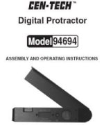
HFprotractor1.jpghttp://www.harborfreight.com/manuals/94000-94999/94694.pdf

You won't find them online anymore, but the stores may still have some.

They also have a knockoff of the unit Miles linked.
http://www.harborfreight.com/cpi/ctaf/displayitem.taf?Itemnumber=95998
 
Miles and Tyler - I'll check into those angle measurers. They look pretty inexpensive! That's always good.

New Year, new update. This has been a productive past couple of days in spite of a few setbacks. I recently connected the high-current shunt resistor (rated at 100 A) in line with the negative capacitor terminal to the Kelly controller:

shunt_resistor.jpg


Now, once I put in its correct resistance value into Cycle Analyst, I will be monitoring accurately-measured amps and power during operation. During another road test climbing hills and such, I had another axle spinout. As some people here already know, the NineContinent BLDC motor (http://www.ebikes.ca/store/store_nc.php) is very "torquey," which I love, as that's the best thing for a start-stop type of bike, but it has a very small axle - a 12 mm threaded bolt with the usual 10 mm separated flats milled into it (http://www.ebikes.ca/store/diagrams/MNCF.PDF). This is a great pain. A torque arm is a must, of course, but my application (throttling and regen braking) causes torquing in two different directions. Here is my junk heap:

failed_arms.jpg


A: Torque washer supplied with NineContinent kit. Its tolerances were fairly tight, but it was not up to the task.
B: I had higher hopes for the AmpedBikes arms, which I used together, one to resist pulling and one to resist pushing. Unfortunately, even these had a sub-par fit with the axle's flats. Even a little wiggle room was opening the door to failure.
C: I took a bar of steel (3/16", or 4.7 mm thick) and milled my own slot into it at the angle I required, using a hand file for a perfect slot diameter. The steel wasn't strong enough as you can see.

This last failure really got to me because it yanked the hall sensor wires and I had to disassemble the hub motor to get things right again. I took some time and came up with a plan to use the leftover steel bar to make a compound torque arm. Here's the raw stock:

steel_bar.jpg


Now, I was going to essentially bolt two flat edges of this steel, which is springy but not as hard as the axle's steel, and apply so much force that it couldn't possibly escape. I should have taken pictures as the machining proceeded but I was moving fast yesterday. Here's the AutoCad drawing:

compound_torque_arm_machining.jpg


The bolts go on either side of the axle, and are 5/16" in diameter (strong). Once the bar was milled down to the right width (0.45" or about 11 mm) and the holes were drilled, I was able to fabricate the longer piece with angled grooves at the top to hold the stainless steel worm clamp. The long arm was first twisted 90 degrees about the Z axis (out of plane) and then bent back to align with the fork. The grooves were aligned with the fork's tube, and I pressed a piece of aluminum as a spacer between the steel and the fork as I tightened the worm clamp. Here's the result:

compound_arm_side.jpg


and a closer view:

compound_arm_close.jpg


It is an extremely tight fit, and I have lots of force applied axially (by the axle nut) and radially (by my twin steel bolts) on the axle. It is not going anywhere. Best of all, the worm clamp holds the arm in place by preventing pulling and pushing (from throttling and braking, respectively).

The day may come when the torque arms are "built-in" to the hub motors, but until then there is always brute force.

Next job: calibrate the current readout and find out regen power and current for downhill coasting and various generator loads while pedaling on a level street. Before the axle issues above, I did pedal around for a while and raise my capacitor voltage from 40 to 48 V. Once I can read currents and get elevation changes, the data will have more meaning.
 
Whoa, an update already. I had to take advantage of the mostly empty streets today and cruise around. I have some neat data now that my shunt resistor is a known and I can now record accurate amps and watts.

First off, I was interested in determining a trend with the bike's speed and the regen amps that would be returned to the capacitor as a function of that speed. To do this, I went down a very, very slight hill (nearly flat) and pedaled to just above the speed of interest with the brake switch on (very slight generator resistance), and used the hand brakes as necessary to get the speed constant. Then, all I had to do was read the displayed current. All tests were with the capacitor module at about 43.6 V.

plot2.jpg


Everyone loves a straight line. Then, I did a few cycling circuits around a block near the building. It is essentially a rectangle - two blocks wide (west to east) and one block long (north to south). There is a stop sign at each intersection. Here the layout:

Leg 1: Sixth Street south. Moderate slope downhill. 0.110 km length.
Leg 2: Bryant Street east. Gentle slope uphill. 0.234 km length.
Leg 3: Fourth Street north. Moderate slope uphill. 0.110 km length.
Leg 4: College Street west to return to start. Gentle slope downhill. 0.234 km length.
Total distance: 0.688 km.

My riding guidelines were:
1) Stay below 20 kph.
2) Use regen braking to slow down as much as possible before each intersection.
3) Use throttle to accelerate to at least 15 kph out of each intersection.
4) Leg 1: Use strong regen braking to keep speed below 20 kph.
5) Leg 2: Bike at speed up gentle slope, using very minor regen braking while keeping speed up by pedaling.
6) Leg 3: Allow motor to do most of the work, pedaling with only a little effort.
7) Leg 4: Pedal easily with moderate regen.

Power usage:
Leg 1: Average 150 W regen (-)
Leg 2: Average 25 W regen (-)
Leg 3: Average 200 W motoring (+)
Leg 4: Average 100 W regen (-)

Circuit data (all from Cycle Analyst):
Initial Voltage: 42.0 V
Final Voltage: 42.3 V
Forward energy: 37.9 mAh
Regen energy: 52.7 mAh
Maximum Speed: 19.8 kph
Average Speed: 14.9 kph
Trip time: 2 min, 42 s
Maximum regen current: 5.45 A
Maximum forward current: 10.58 A
Minimum module voltage: 41.6 V

The torque arm performed like a champ. Riding around all afternoon like this wouldn't wear me out either. I think that as long as the trip doesn't involve a huge net elevation change, the capacitor can be adequately charged by the person riding the bike.
 
More torque arm fun... the custom-made torque arm I described earlier failed by bending out of shape along the 1/2" thick stem, so I made another, wider (1") one... which failed later on by spinning out. My stator bolt has taken a lot of punishment during the various spinouts, getting rounded off and losing threads in the process. Since you can't replace the bolt, I was looking at needing to get a whole new motor. Today I tried a long shot idea to fix it up: I drilled a hole from one side to the other of the stator bolt (the side without the wires coming out, from one flat side to the other). I had to take the motor apart to get things lined up right in the drill press, but here's the result:

DSC00012.jpg


The hole is big enough to let a threaded quarter inch bolt through (~0.243").

DSC00013.jpg


I reassembled the hub motor:

DSC00014.jpg


I had also drilled a matching hole in each side of the external torque brace (from Mark II):

DSC00015.jpg


Here is everything bolted on, without the spacers (to keep the first failure from re-occurring):

DSC00016.jpg


And here's the whole setup, including spacers and the worm clamp on the fork.

DSC00017.jpg


The test drive was a success, and if this thing manages to fail again, I quit! Long live Torque Arm Mark III.
 
I love the super capacitor avatar
 
CJG, this is all very exciting! What we all want to know is what it feels like: how hard were you pedalling? In a sense, you got more than 100% regen. Of course, that's because you are pedalling to add energy. Are you left with the impression that this is either a) a practical ebike with out a battery or b) would make a worthwhile addition to an ebike with a battery? If either of these are true, what is the possibility of others building one of these ebikes - in other words, can one buy the ultracapacitor and is it prohibitively expensive compared with say LiFePO4 cells?
Can you think of experiments which take your pedalling strength and weight out of the assessment? Are you planning any test with a battery as well as ultracapacitor? Any longer trips planned? With video (this will give an impression of your effort)? How about a test against another ebike - one circuit with you on your bike and someone else on a known bike, followed by another circuit where you swop bikes?
 
Paul, thanks for putting this into words; I have been wondering on and off about all of these things but I haven't taken the time to think in enough detail up to now.

paultrafalgar said:
What we all want to know is what it feels like: how hard were you pedalling? In a sense, you got more than 100% regen. Of course, that's because you are pedalling to add energy.

The propotional control of the regen brake is giving me a lot of options here. Some background might be necessary since we're talking about effort... I've been biking through city traffic for distances of around 5 miles (round trip) on a regular bike for about four and a half years now. That kind of training is really more akin to strength training than endurance, with all the stop and go. I also do weight training a couple of nights each week with traditional olympic lifts, incuding squats (I'm not even bronze medal material though :D). That gives you kind of an idea of my general fitness level. I feel that I can comfortably (feeling as if I was riding a wide-tired mountain bike) cruise at 20 kph while sending 75-100 W back to the capacitor when I'm on a mostly flat street. For my usual voltage range, this is a bit less than 2 A of regen. Honestly, I don't feel any discomfort or unusual effort. Coming to a stop is capturing things less efficiently, due to phases shorting together (or something like that, I'm still reading about it). I feel I really make my best headway pedaling against low resistance at cruising speed.

Are you left with the impression that this is either a) a practical ebike with out a battery or b) would make a worthwhile addition to an ebike with a battery? If either of these are true, what is the possibility of others building one of these ebikes - in other words, can one buy the ultracapacitor and is it prohibitively expensive compared with say LiFePO4 cells?

I wouldn't have known how to best answer this without some real comparison with the battery types out there; I had no idea that some 48 V battery packs were as heavy as they are. Not counting the hub motor, I've added about 35 lbs total to the bike's weight. I think that compares pretty well with other ebikes (please correct me if I'm mistaken). I would say that both of these [(a) and (b)] are true, but probably I would suggest 48 V for a battery-free ebike (like my prototype) and a 36 V capacitor module matched in parallel with a 36 V battery pack for the mixed setup you suggest, or 24 V of each to save a bit of weight. With this kind of regen, city biking with this bike will mean that I won't ever need to charge from the wall as long as I don't leave the bike sitting around for a month. What I'd really like is a rear-front wheel linked dyno so that I could charge the cap while sitting still before a trip (to top it off). For now I have to stick to through-the-road regen, which means I'll ride around in circles.

The immediate concern closest to my heart is the way things bounce around behind me when I hit a bump. It's all locked down pretty solidly, but it still scares me sometimes.

*Edit: I just realized I didn't answer that last question. A 3000 F, 2.7 V boostcap cell costs about 115 USD from Maxwell. I have 18 of them in series to make my module, which is a pretty hefty price tag (2070 USD) if it was purchased new (mine were free, donated to my hybrid research by the good doctors at Maxwell Tech). Making a 36 V stack wouldn't be as bad, and 24 V would be quite reasonable (at around 1000 USD). The thing is, they will last PRACTICALLY forever (that's for you, Toorbough :lol:) and I expect that the prices on ultracaps will continue to come down as more companies get into the mix. As I mentioned before, they've already come down a factor of 10 (dollars per stored joule) over the past 5 years. I really like the outlook.

Can you think of experiments which take your pedalling strength and weight out of the assessment? Are you planning any test with a battery as well as ultracapacitor?

It's going to be hard to take those values out without a propulsion model. I need one of those to be refined for use in the paper I hope to get out of this, so I will see what I can do. It will probably be a data fit approach; I can add my mass to that of the bike, but quantifying pedaling power is going to take some creativity. I realized that we have one perfectly flat area nearby - there's a running track at the high school just to our west. I am going to sneak out there with some students and get some zero-grade data. I think that a battery-cap mix would be great. I'll take any suggestions of a good, long-life, light 36 V pack that someone could recommend.

Any longer trips planned? With video (this will give an impression of your effort)? How about a test against another ebike - one circuit with you on your bike and someone else on a known bike, followed by another circuit where you swop bikes?

I want to ride the bike back and forth from home soon. I am thinking about getting one of those helmet-mounted cameras that Nashbar offers (http://www.nashbar.com/profile.cfm?sku=21385). There is a guy in EE here that has an older NiCad, external motor-powered bike, we even might be able to race... :lol: Thanks as always for the interest & support.
 
JCG wrote, about the torque arm struggle:

"if this thing manages to fail again, I quit! "


PLEASE don't quit! We have so much to learn from you and your project.

It's so sad, with all you've accomplished on electric matters, that this mechanical thing is giving you so much frustration. Maybe you need to go with a different motor?

My front Crystalyte 408, without a torque arm, running at 66V on A123s, over hundreds of km, has had no such problems - and I push it quite a bit coming up the hill to my home (but I never attempt a quick acceleration from a stopped position).

Justin, at ebikes.ca, went all the way across Canada on an old mtn bike/extracycle using a front Crystalyte 5304 and stock torque arm - secured by what seems to be a rag (judging from pics) to the fork arm.

Maybe others using Nine Continent motors will chime in with their experiences; seems like the NC shaft is too weak for the torque the motor generates?

(I am currently considering torque arm options for my Big Dummy with a front CL 5304, and I'm grateful that you shared your torque arm experiences. Thanks!)

Larry
 
Don't worry Larry, I'm slightly more than cautiously optimistic that this time it'll hold! In fact, I'll be going out for a spin here in a few minutes. I just hope no one else has to do that many weird things to their axle...

I wouldn't really say that the NC motors have a weak axle, in fact it may be the strength of that axle that ironically spun through my steel but also means I can still use it... it spun out, and in sequence vented its wrath on my fork droupouts, defeated the torque washer, rolled through the Ampedbikes torque arms (simultaneously), my custom torque bar, bent the heck out of Torque Arm Mk I, pried open Mk II and in the process all it lost was some threads. I think the real complaint is that with a 12 mm nominal bolt diameter, cutting flats to get 10 mm across is just too small of a "flat" area for any passive (non-clamped) torque arm to handle. Compared to the 12 mm axle, the 14 mm axles increase the flat width from 6.6 mm up to 9.8. that extra area can really help prevent spinout! Plus, it's a lot harder to spin a 14 mm rounded edge through a ~10 mm wide slot than a 12 mm rounded edge, especially after the threads are gone. Combine all that with the extreme torque the NC motor can put out, and in both directions thanks to regen, and I was asking for trouble.

I would love to hear other NC users share their stories, though. Good luck with your torque arms, Larry! I hope you have success in Round 1 (not 6, like me :D )
 
Do you know how they make the caps? Are there layers of plastic and foil?
 
JCG said:
...
Can you think of experiments which take your pedalling strength and weight out of the assessment? Are you planning any test with a battery as well as ultracapacitor?

It's going to be hard to take those values out without a propulsion model. I need one of those to be refined for use in the paper I hope to get out of this, so I will see what I can do. It will probably be a data fit approach; I can add my mass to that of the bike, but quantifying pedaling power is going to take some creativity. I realized that we have one perfectly flat area nearby - there's a running track at the high school just to our west. I am going to sneak out there with some students and get some zero-grade data. I think that a battery-cap mix would be great. I'll take any suggestions of a good, long-life, light 36 V pack that someone could recommend.
One thought: If you had access to a rolling road you might be able to take out those parameters. That rolling road would have to measure the forces it was applying to your ebike, so you would be able to quantify your inputs and outputs. Some maths for the students to do? 8) :lol:
Edit: maybe you could fabricate a rolling road with some rolling pins and use an anchored spring balance to measure the force you were pedalling with? :lol:
 
Back
Top