Some thoughts you may want to investigate:
I bought 2 brand new sensors from Aliexpress. Unfortunately i don't have the xiaomi qicycle bike itself and i can't measure sensors input voltage coming from the controller.
Do the AE sale pages include a pinout for the sensor to show you which wires are which, and what voltage(s) to input, and what their outputs should be?
We can't check this for you as you haven't provided a link to the source page yours came from; we can only guess as we have no data outside what you've posted in this thread.
")
However sensor have 3 wires like regular throttles (red,black and white)
Unfortunately, that doesn't mean anything other than that they have three wires. Doesn't tell you anything about voltage/current required, or what signal types they use. There are sensors that have three wires but use digital output, or even digital I/O that is addressed that requires a query by the bus the data line is connected to in order for the sensor to output anything.
If it always has the same voltage on the output pin (assuming you are certain that it *is* the output pin, and that the pins you are connecting supply voltage and ground to are actually the correct pins as well; any miswire could damage a sensor and leave it inoperative even when rewired correctly).
Hopefully Stancecoke is correct and these are clones of the TMM4...but they may not be.
If these are supposed to be analog output, and they are clones of the TMM4, they would not have 5v on the output when no force is applied.
IDbike develops and produces components for electric bikes, such as torque sensors, controllers and displays.

www.idbike.com


The TMM4 Sensor
The TMM4 sensor has the world's best price performance. It is a patented development of IDbike, and can be used for measuring the crank torque of the cyclist. Because of its high precision this sensor can be applied in electric bicycles as well as in power measurement systems. Here you can find is a nice example of the application of our TMM 4 sensor
Due to the sensor’s low profile the rear drop out can be designed so that it covers the sensor completely. This way the sensor is fully protected and the appearance improved.
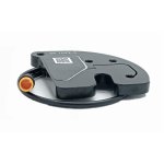
The TMM4 sensor consists of a housing of engineering plastic, which holds a printed circuit board (pcb) , a magnet and a small set screw, which is used to calibrate the zero value
The sensor, mounted on the sensor plate, measures the deflection of the plate caused by the chain force. This, in turn calculates the pedal torque of the cyclist. The deflection is detected using Hall technology and is maximal 0.1 mm.
The sensor is connected to the control unit with a 3 wired cable. The sensor can be hardwired or can be connected with a small connector.
The printed circuit is protected against moisture, salt and dust, by a special coating. The sensors are tested by immersion - in operationt - in salt water for at least one week.
And of course our sensors are tested under extreme outdoor conditions:
The sensor units are available in 2 versions:
Medium sensitivity for sportive bicycles, such as mountain bikes and speed pedelecs
High sensitivity for normal bikes like city and touring bicycles
Soon IDbike will be able to deliver new generation sensors, which will be smaller, completely flat, and with even better stability.
RegularCompactSC
The TMM4 Regular is the actual sensor unit, the compact will be available in the end of 2018, and the Super Compact, to be used with through axle in 2019.
Specifications TMM Sensor Unit
Supply voltage:
5 V
Output voltage: 0,1 V- 4,9 V
Measuring range sensor unit: 120 Nm ( High sensitivity) / 300 Nm (medium sensitivity)
Sensitivity TMM sensor unit:
40 Nm/V (High sensitivity)/ 100 Nm/V (medium sensitivity)
Tolerance on sensitivity: < 3 %
Allowable range ZTV (zero torque value): 0,5-2 V
Temperature influence: < 1 mV/ ºC
Electrical disturbance: < 10 mV
Effect of moisture: < 10 mV
Operational temperature: -10 - 60 ºC
Storage temperature: -40 - 85 ºC
Durability: At least 10 million cycles
Protection Class: IP66 >> protection aigainst water and dust
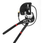
I haven't installed sensor on the bike yet i am just experimenting by applying force with adjustable pliers.
I can't tell if the forces applied are the same as the way the chain would pull. If they're not, they may not cause output as expected.
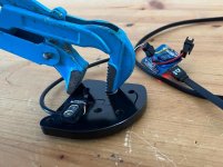
I haven't installed sensor on the bike yet i am just experimenting by applying force with adjustable pliers. I tried switching white and red colors and KTLCD7c display keeps showing "throttle error"
Yes it is always giving 5V output. I also tried connecting to an ESP32 today. It is always outputting the same value
A controller *should* show an error for any throttle signal that is above it's maximum throttle input value (usually around 4v or so).
Are all the tests you've done with it connected to a controller, MCU, etc?
Or have you done any testing with just the manufacturer-specified supply voltage connected to just the manufacturer-specified supply pins, and measuring the otherwise-not-connected manufacturer-specified output pin with a voltmeter or multimeter?
Note that swapping wires for supply voltage input from what they should be can damage the part.