Sattva Ram
100 W
- Joined
- Jan 4, 2020
- Messages
- 271
What's the max amp for the 200 sp/2? Does anyone run it at 350 line current?
¿Resolvió su problema? Si no remítase al Taller La Fábrica en la Habana, Cuba.h
Ami em 50, actualice con el archivo incorrecto y quedó muerta la controladora, gracias
Thanks a lot for your help.That usually indicates that the controller is setup to respond to a lower throttle voltage than the throttle actually outputs.
If the throttle signal wire on the controller is left unconnected, does it still behave this way?
When signal wire is disconnected, controller is in low voltage protect. Motor stops immediately.
If so, there's something wrong in the controller, either:
--a hardware issue with the throttle signal input path creating a voltage at the MCU pin for that signal above the minimum response voltage,
--a software bug where settings don't correspond to reality for throttle voltage limits,
--a setting turned on for something like a "freewheeling current" where some minimum phase current is always applied to the motor (this should normally not happen except when the motor is spinning, but if it's not well-designed software it might do it all the time).
If it does not have the problem without the throttle signal attached, it's probably too high a signal voltage on the input at throttle "off".
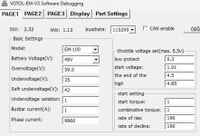
Some controllers have actual throttle voltage ranges that can be set, and some just have a throttle type choice (like pot vs hall), and some do not have any options. I don't know what your software allows you to set, so you'll have to check for this.
Thanks a lot. Finally got it working.That usually indicates that the controller is setup to respond to a lower throttle voltage than the throttle actually outputs.
If the throttle signal wire on the controller is left unconnected, does it still behave this way?
If so, there's something wrong in the controller, either:
--a hardware issue with the throttle signal input path creating a voltage at the MCU pin for that signal above the minimum response voltage,
--a software bug where settings don't correspond to reality for throttle voltage limits,
--a setting turned on for something like a "freewheeling current" where some minimum phase current is always applied to the motor (this should normally not happen except when the motor is spinning, but if it's not well-designed software it might do it all the time).
If it does not have the problem without the throttle signal attached, it's probably too high a signal voltage on the input at throttle "off".
Some controllers have actual throttle voltage ranges that can be set, and some just have a throttle type choice (like pot vs hall), and some do not have any options. I don't know what your software allows you to set, so you'll have to check for this.
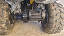
So it turns out the phase wires were backwards, is this common? It's the second controller this has happened with...
There is no other post by you on this forum (you joined today about 3 hours before this, your first post, so unless you're referring to a post on some other forum you didn't link to.... :/My Original post:
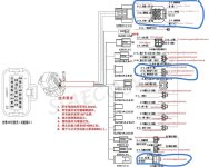
(left to right = Battery-red, blue, green, yellow, Battery-black).
Yes, all hall cables are correctly connected. I have cheched all the possible color combinations but only yhe same color match works well.Are all the halls operating correctly? (while connected to the controller, controller powered up, manually turning the motor shaft (by turning the wheels?), you should read around 0-0.8v whenever a hall is active, and around 4-5v when they are not (assuming the controller pullups are 5v when not connected to the motor).
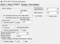
I think it's more like 60 degrees. Or do you mean the hall shift angle in the votol debug software?Yes, all hall cables are correctly connected. I have cheched all the possible color combinations but only yhe same color match works well.
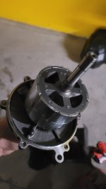
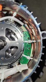
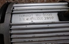
I also teardown the motor to see the pole pair numbers and hall sensor angle. Photos are attached. It seems 4 pole pairs and 120degree. But motor spins unreliable with these settins.
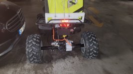
Is the nonworking controller configured identically to the working one?Just out of interest, the same setup works flawlessly on my SurRon with the other EM-150 controller...

Do have firmware for em-100? Could you send to killaji@gmail.comI see... let's do something. Sometimes votol controller s gets corrupt. In this case, the best is download the firmware, then send a well known good config... as base config. Then tune the values. Give some email and i will send you the firmware .bin and my base config...
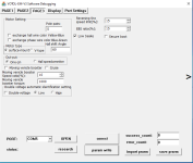
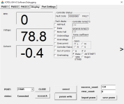
Thank you, it works, exactly what I needed, I wonder if you still develop this application?Thêm em150_viewonly apk
View attachment 329320
Merhaba, bin dosyasına ulaşabildiniz mi? Benim de ihtiyacım var. TeşekkürlerHello, I need the original last bin file of votol em150. please let me. moncel1987@hotmail.com Thanks a lot.