What BMS to use for 22S high discharge

TerrySavace

100 mW
Joined
Feb 4, 2021
Messages
41
Hi all,

Just wondering if you have any suggestions on what BMS to use for a 22s14p sony VT6 setup. I see a lot of 22s BMS's only have 100Am discharge? Do ant do one?

Thanks in advanced!

Terry
 
Just wondering if you have any suggestions on what BMS to use for a 22s14p sony VT6 setup. I see a lot of 22s BMS's only have 100Am discharge?
What job does the pack have to do for you? Without knowing the current the pack must be able to supply, and for how long it's tough to say which one to use.

How hard do you want it to be able to push the cells, vs how much protection would you like to provide for them? (the harder they are pushed, the shorter their lifespan will be)

Also, what other features do you need it to have? Programmability? (if so, what functions do you need to be able to change? Do you need it to be alterable from your phone/etc, or just at a home computer? Etc.) Do you need on-bike access to the BMS for information about the cells, etc? Do you need to be able to turn the BMS on and off?

Note that if you really need high current, then if the cells can handle it you can use a contactor based BMS instead of the common FET based types, and then your contactor can be whatever you need it to be (up to whatever the BMS is designed to control). There's a recent thread with info about those, I think it's in Eastwood's First Battery Build. Other threads, too, dont' recall the names.
Thanks for your reply. Its a 22s14p sony VT6 battery, powering a qs205 motor via a nucular electronics 24f controller. I want to be able to check cells and provide protection to the bike - hence will use an ANT controller
 
Thanks for your reply. Its a 22s14p sony VT6 battery, powering a qs205 motor via a nucular electronics 24f controller. I want to be able to check cells and provide protection to the bike - hence will use an ANT controller
You still need to define the other things I mentioned, to know what protection to use. If you don't know what your limits need to be, you can't protect against exceeding them.

"provide protection to the bike" doesn't really mean anything--you have to define what protection specifically you want to happen, and how you want it to happen, and at what limits. Are you protecting the motor or controller? The controller has it's own limits to do those. The wiring? Fuses and circuit breakers are there for that. The cells? The BMS is there for that. Etc.

I haven't seen a controller by ANT, but I have seen BMSes by them. Is that what you're referring to?


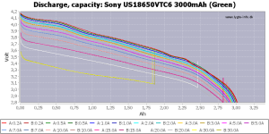
I couldn't find a VT6 cell in the tests on the linked site below, but found two VTC6, the link is hte first one so all math/etc below is for that. If your cell is different you'll have to do the math for that one based on whatever testing or specsheet there is for it.
1682367401626.png
Looks like it *can* be used at high currents, but it sags a lot at those and has much less capacity available that way. More sag means less actual power (watts, V x A) for your system, so beyond some current you will get more power by drawing *less* current until voltage sag is lessened enough to give more watts with the current being drawn.

At max and near max currents, capacity could be nearly cut in half.

14p could theoretically do 30A/cell x 14p = 420A, but I would recommend against that except for short bursts based on the above testing chart. That's probably the limit you'd want to set in the BMS, to keep it from being damaged.

For continuous it looks like it'd be better to stick with 10-15A or less per cell, which would be 140-210A for the pack. For this, you would set the controller's current limit to this.

THe BMS needs a max current limit of whatever you want to protect the cells against, because it will need to shut power off if this current is exceeded. You want the controller to limit well below this, because you do not want to shut power off while riding--if you're in traffic when that happens it could be bad.

Whatever current limit you set for the max possible before shutdown, you want a BMS capable of significantly more than this, so it is not stressed or heated up by usage at that current--you want it to be able to reliably supply all the current you need, *and* reliably shut off current if a problem happens so the pack isn't damaged (which can create a fire risk).

I can't know how much power your system will take, for that you must define the job your system must do for you and then determine how much power that will actually take. The ebikes.ca motor simulator can help you do that (even without the actual parts you have, you can guesstimate what they are and use the custom fields to simulate them). Instructions on using it are below the chart there.

If you don't want to do that then for protection's sake you should assume max current capabilities of the controller, whatever those are, as your max protection limits.
 
Thanks for your reply. Its a 22s14p sony VT6 battery, powering a qs205 motor via a nucular electronics 24f controller. I want to be able to check cells and provide protection to the bike - hence will use an ANT controller
You still need to define the other things I mentioned, to know what protection to use. If you don't know what your limits need to be, you can't protect against exceeding them.

You can choose to just buy parts that seem like they'll work but if you don't actually run the numbers, you may end up with parts that can't do the job you need them to do, and a bike that doesn't do what you want, and have to spend more money on different parts once you do know what you need. ;)

"provide protection to the bike" doesn't really mean anything--you have to define what protection specifically you want to happen, and how you want it to happen, and at what limits. Are you protecting the motor or controller? The controller has it's own limits to do those. The wiring? Fuses and circuit breakers are there for that. The cells? The BMS is there for that. Etc.

I couldn't find a VT6 cell in the tests on the linked site below, but found two VTC6, the link is hte first one so all math/etc below is for that. If your cell is different you'll have to do the math for that one based on whatever testing or specsheet there is for it.
View attachment 333191
Looks like it *can* be used at high currents, but it sags a lot at those and has much less capacity available that way. More sag means less actual power (watts, V x A) for your system, so beyond some current you will get more power by drawing *less* current until voltage sag is lessened enough to give more watts with the current being drawn.

At max and near max currents, capacity could be nearly cut in half.

14p could theoretically do 30A/cell x 14p = 420A, but I would recommend against that except for short bursts based on the above testing chart. That's probably the limit you'd want to set in the BMS, to keep it from being damaged.

For continuous it looks like it'd be better to stick with 10-15A or less per cell, which would be 140-210A for the pack. For this, you would set the controller's current limit to this.

THe BMS needs a max current limit of whatever you want to protect the cells against, because it will need to shut power off if this current is exceeded. You want the controller to limit well below this, because you do not want to shut power off while riding--if you're in traffic when that happens it could be bad.

Whatever current limit you set for the max possible before shutdown, you want a BMS capable of significantly more than this, so it is not stressed or heated up by usage at that current--you want it to be able to reliably supply all the current you need, *and* reliably shut off current if a problem happens so the pack isn't damaged (which can create a fire risk).

I can't know how much power your system will take, for that you must define the job your system must do for you and then determine how much power that will actually take. The ebikes.ca motor simulator can help you do that (even without the actual parts you have, you can guesstimate what they are and use the custom fields to simulate them). Instructions on using it are below the chart there.

If you don't want to do that then for protection's sake you should assume max current capabilities of the controller, whatever those are, as your max protection limits.
May i just thank you for your time on writing all of this out - its been VERY helpful!
 
Back
Top