what is cogging torque?

goatman said:
if you go to ebikes.ca, all axle motor page it shows cogging effect with different magnets

https://ebikes.ca/product-info/grin-products/all-axle-hub-motor.html

if you go to phaserunner page theres a field weakening link that brings you here

https://endless-sphere.com/forums/viewtopic.php?p=984725#p984725

which makes me think that field weakening is like a delta/wye switch, inject enough amps and double your speed.
im going to have to go read up on this to see if that is actually what foc is, a delta/wye switch

makes sense greater cogging with stronger magnets, and the cogging torque looks linearly produced related to rpm/frequency, as apposed to exponential with eddies.


i dont know how field weakening is done through programing but i dont think it would relate to cogging. cogging seems entirely dependent on the motor design. cogging is a fundamental, simple, "hardware" issue. it needs an explanation based on the basic laws of physics as apposed to more complex programing stuff. so i believe

but what causes cogging? does it produce heat? it makes more sense it being a form of hysteresis being linear. any leads?
 
goatman said:
im reading the field weakening thread right now. 51pages :shock: what youre asking im seeing being mentioned

not that i know what im reading.

ive heard of programing that will eliminate cogging through powering phases at just the right moments throughout the motor's rotation so as to eliminate the cogging by countering it (jason and grin do that), which maybe is similar to implementing field weakening, but that's still just countering the cogging as apposed to explaining what it is. every loss in a motor can be fully explained attributing it to a law of physics but cogging gets a hand-wave explanation. does it even produce heat? if it is producing heat by what means?
 
I'm doing a service on my kuburg and theres now bearings going in the motor but with it in my hand the cogging is unreal I have split the chain and to pull it out took some oomph easy 4kg braking force to spin the motor.

When I ride it I've always noticed it's very eager to slow on decel it's much like a 4 stroke to ride and feel where as mxus 3k felt like a freewheel compared to this innruner I've seen people feed them 14kw so it's quite capable for its size and weight but the drag is unreal.
 
When there a chucked magnet i suppose there will be shit loads of resistance that will do the trick pyle of shit.
 
I still can’t find if cogging torque is even a loss other than like a ball on an undulating track that just gets stuck in the dip as can’t make it over the next hill. There’s a loss in that case but not when the motor has the momentum to overcome the next hill


How would a test be setup to see if cogging is a continuous loss? I’m thinking coupling the motor shaft to a dyno and figuring its losses then vs when powered would do it but cogging torque is said to be overlaid on a powered motor’s output torque which makes me wonder because I’d think the stator iron being electrified and polarized, creating a pull and push, would not cog as apposed to the nonelectrified stator’s pull.
 
[youtube]esUb7Zy5Oio[/youtube]

This is a good video to understand bmf.

More poles a motor has the motor will align rotor and stator more times per 360 degree mechanical rotation.

The stronger the bmf linkage more force needed to overcome it.

So typically motors with heavy cogging effect will also have a very powerful torque figure when power is being applied.
 
High cogging, and generally few poles, doesn’t reveal how much torque a motor can produce though.

This new hybrid motor has a weaker back emf (back voltage) producing less eddies n hysteresis but there's no mention of the cogging. I assume the cogging is low due to it being partially a reluctance motor and also with the shaping of the magnetic field
 
Hummina Shadeeba said:
Cogging and torque the motor will put out arent related.

Yes they are directly linked thats why the ipm reluctance motor is a design improvement and chosen, if you bothered to watch the video you may learn something.

The engineering priciple is clearly shown, you can't argue with physics.
 
from my understanding of the vid there was no cogging torque mentioned and the motor was chosen because it gives the starting torque of a pm motor but the low high speed losses of a reluctance motor.


a reluctance motor has no cogging but the cogging torque of a pm motor is not necessarily and rarely related to the torque it can put out. if you skew the magnets or the stator teeth of a pm motor it will produce less max torque, produce greater iron losses, and also reduce the cogging. That's an example of cogging being reduced along with the torque output but generally more magnets and teeth is less cogging, greater positional control, and you can use smaller magnets and thereby slightly increasing the airgap diameter thereby giving you a slight increase in torque in that bigger lever. so less cogging would generally equate to more torque if the motor was designed well. But thats a pm motor and this is a hybrid where the rotor magnetic field is better controlled. i dont see a comparison of the magnetic field shape with a typical pm motor but i think in this hybrid the field only comes in contact with the stator at the 45 degree angles the vid talks about and that will reduce the iron losses and the cogging

this hybrid motor looks to have very low cogging as it looks so much like a reluctance motor with the rotor having a continuous iron exterior. but it only has 4 poles which would be very high cogging torque in a typical pm motor.


in the vid at like 5 min it talks about the loss from back emf..but then says "furthermore the magnets produce eddy losses".. is there a loss from back emf separate from the eddies and hysteresis that are being produced in the material near the moving magnets? i think a voltage produced in the windings by the back emf is not a loss unless it makes a complete circuit and thereby producing current. the powered windings would have their own emf which must be greater than the back emf to get current to flow but is there any loss there in that magnetic field to magnetic field interaction?
 
I dont mean to sound like a nob and can be snappy on times and apologise, Its the bemf that is creating drag when there is no power applied that was shown in the vid.

It also shows that the rotors magnetic field and stator aligns itself through out the mechanical 360 rotation more pole pairs more this happens per 360 mechanical rotation so the bemf sweet spot happens more times and stronger the magnetic linkage between them more current is created and harder it is to overcome so less pole pairs will have a stronger magnet field but less times it will align per rotation.

If you was to apply a lever to the motors output shaft and add weight to get it to break free and turn to the next alignment location this is the torque thats required to turn the motor (cogging torque) even when the phases are firing the first part of the input is soaked up to overcome this internal force but as the video shows its only the first phase fire as soon as the rotor and stator align the controller moves the phase angle around the stator coil and the rotor is locked to that postion as its a synchronous motor.

So cogging torque is just the initial movement of the motor soon as the rotor and stator align its just a case then of keeping them aligned so the field rotates and the rotor is locked to it in this respect sensored motors shine becuse theres an automatic detection of the rotor snd full torque can be apllied from standstill where as a sensorless needs to do feed back math on the phases to work out where the rotor is aligned.

The magnets losses are part of that missing 7% efficiency i suppose as the ipm has incresed efficiency only 4%and there was mention of segmented magnets to keep their internally eddy smaller.

You raised some good points and clearly have some decent knowledge im sure it will click with you soon enough, i can't say i know alot about motor design and choices but just like to observe a few bits and bobs.
 
As I understand it back emf isn’t a drag or a loss in a motor. https://openstax.org/books/college-physics/pages/23-6-back-emf
The only drag or losses in a motor are copper loss, iron losses (hysteresis and eddies),bearing friction, and air friction.

Cogging torque in its most obvious form is the resistance to a moving unpowered motor due solely to the interaction of the magnets to the iron. The moving magnets could induce a back emf in the motor but that’s not cogging and also need not be any loss or drag.

((Ive had trouble for years now believing this loss of momentum due to cogging, which can be a lot, is dissipated solely through eddy currents or hysteresis as generally the more magnets a motor has the greater the iron losses yet less cogging torque. Also cogging, if net zero loss when the motor is able to overcome its magnetic hills, would produce no drag that would be called cogging until the motor slowed enough to finally get stuck in a valley.))


And would cogging be eddies or hysteresis? If eddies then with its exponential increase with erpm they would become huge given how strong they are at the slowest speeds. Hysteresis makes more sense in their being linearly produced as cogging torque seems to be.

Where’s @liveforphysics or someone to set me straight?! Been years I stew on this.

wondering what experiment would reveal what cogging torque is or if it's even linearly produced i was thinking maybe comparing the current needed to spin an unpowered motor some speed vs that same motor powering itself to that speed could maybe show a difference. if not and it took the same current maybe the cogging torque is still just as great when the motor is powered though and regardless of the push and pull of the electromagnets on the magnets the pull of the magnets to the iron, cogging, is still there overlaid on the output.
 
There aren't significant losses caused just by cogging. All the losses are like you stated, eddy currents, hysteresis, bearing friction and windage. Cogging might slightly increase bearing friction as there will be parts of the cycle where bearing loads are higher than average, but it's not significant.

I did a test once using a magnetic coupling. Two magnets that spin on bearings with a gap between them. One magnet was driven by a motor and I measured the current to see the load change. With the other magnet, I could increase the load until the magnetic coupling lost lock and it started cogging. If I held the other magnet fixed, the motor current was very nearly the same as when the other magnet was taken away (no load). The cogging was pretty strong with the coupling. I'm sure there were some eddy currents in the magnets but they must be really poor conductors since I didn't measure much.

Another test would be to try a skewed stator that has no cogging and compare to a straight one the exact same size with cogging.
 
I think ur saying with ur test of two magnets that it cogged a lot but when spun up to a speed the momentum carried it through and there was very little current needed to spin it. Good simple test. Be nice to make a really badly cogging magnet setup as u did and get accurate current measurements at different speeds. I think my wattmeter is accurate enough. then make the same magnet geometry but with sliced magnets to cut the eddies and see how that goes. If u don’t I will! Maybe u already have?


As far as skewed vs non-skewered I posted just such a comparison in this thread or another related thread in a study I found. I’ll post it again and the skewed stator produced more iron losses and less cogging. The shaping of the field and what’s really going on can greatly vary but I think that result is the norm
 
fechter said:
There aren't significant losses caused just by cogging. All the losses are like you stated, eddy currents, hysteresis, bearing friction and windage. Cogging might slightly increase bearing friction as there will be parts of the cycle where bearing loads are higher than average, but it's not significant.

I did a test once using a magnetic coupling. Two magnets that spin on bearings with a gap between them. One magnet was driven by a motor and I measured the current to see the load change. With the other magnet, I could increase the load until the magnetic coupling lost lock and it started cogging. If I held the other magnet fixed, the motor current was very nearly the same as when the other magnet was taken away (no load). The cogging was pretty strong with the coupling. I'm sure there were some eddy currents in the magnets but they must be really poor conductors since I didn't measure much.


when your magnetic coupling lost it's lock and I guess would be cogging, you say the current draw was very nearly the same as when no magnet there but what did you see and how accurate?
 
Hummina Shadeeba said:
when your magnetic coupling lost it's lock and I guess would be cogging, you say the current draw was very nearly the same as when no magnet there but what did you see and how accurate?

It was a while ago, but I was using a small ironless brushed motor as the driver and had a very precise current measurement. I was specifically looking to see if I could reliably detect loss of lock on the coupling. It was pretty obvious from the current measurement.

Another way to look at it is where does the energy go? If there is no mechanism for loss, then there will be no loss. In a motor, coasting losses are mainly hysteresis and eddy currents in the stator. Cogging doesn't really change this.
 
fechter said:
Hummina Shadeeba said:
when your magnetic coupling lost it's lock and I guess would be cogging, you say the current draw was very nearly the same as when no magnet there but what did you see and how accurate?

It was a while ago, but I was using a small ironless brushed motor as the driver and had a very precise current measurement. I was specifically looking to see if I could reliably detect loss of lock on the coupling. It was pretty obvious from the current measurement.

i was misunderstanding what you were doing i think. i dont know what this coupling is but i assumed it was just like a magnet motor with really bad cogging.

Another way to look at it is where does the energy go? If there is no mechanism for loss, then there will be no loss. In a motor, coasting losses are mainly hysteresis and eddy currents in the stator. Cogging doesn't really change this.


maybe its a terminology misunderstanding on my part and "cogging torque, as you feel that ratcheting in your hand and can see its form on the output of the motor, always there, but it has net-zero effect on the output, and the drag i feel pulling me back from a good coast on a hub motor is hysteresis and ive incorrectly assigning it to cogging torque?
 
Hummina Shadeeba said:
maybe its a terminology misunderstanding on my part and "cogging torque, as you feel that ratcheting in your hand and can see its form on the output of the motor, always there, but it has net-zero effect on the output, and the drag i feel pulling me back from a good coast on a hub motor is hysteresis and ive incorrectly assigning it to cogging torque?

I think that is correct.

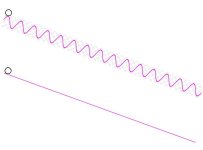
Here's another way to look at it. Imagine a ball rolling down a ramp. One ramp is straight and one ramp is wavy. On the wavy ramp, once the ball gets going fast enough to overcome the next hill, it will go all the way down and won't have significantly more losses than the straight ramp (assuming it doesn't get going fast enough to "jump").

Cogging analogy.jpg
 
fechter said:
[
Cogging analogy.jpg

Where’d you get this analogy drawing or you make it?

With the ball on track analogy, if using a flat track the speed and mass of the ball can determine what valley it eventually gets stuck in. The ball’s momentum determining how far it will go on the level track. I don’t understand what would be analogous to the downhill track but i like the analogy the most if were a slight up hill. what is the slight uphill analogous to?

if I skewed the magnets and resulted in minimal ratcheting in the hand it will also coast at slow speeds as if it were almost only bearings in the motor. Some paper I find and posted here somewhere showed more iron losses not less when skewing. Maybe other variables.


Is this resistance following the rpm in a linear way? I’m feeling it does.
 
I just drew the picture as a concept.

I have one bike with a direct drive hub motor and for sure there is a lot more drag than my other bike that has a mid drive and freewheels downhill. I attribute most of this to iron losses in the stator. It does vary directly with speed. You could avoid this by using an ironless motor, an induction motor, or a switched reluctance motor, all of which are more expensive and harder to make. I think an induction motor wouldn't be all that hard and they can be pretty efficient.
 
i didnt do any math but hysteresis seems a loss at much higher frequencies than would be noticeable when coasting down the street at 5mph.

a good test would maybe be to replace the stator with metal with a tighter or looser hysteresis loop to compare but i dont have that available.

id think the switched reluctance motor would be the easiest and cheapest to make since it has no magnets.


https://www.horizontechnology.biz/blog/hysteresis-loss-in-dc-motors-bh-magnetization-curve

but with an unpowered motor...the magnetic domains in the teeth are not pushed anywhere close to their polarity extremes. the flipping of polarity back and forth with the unpowered motor would be less than if powered.
 
I still haven’t found evidence that cogging’s loss of momentum is converted to iron losses and looking at common methods of reducing cogging, such as skewing, cause greater iron losses generally.

What of the possibility that just as a magnet can be seen as an endless potential energy source that just needs to be oriented correctly, the magnets in an unpowered motor would be an example of the magnets being oriented incorrectly. A magnet motor is able to utilize the magnets’ potential energy when powered adding to the output torque essentially for free as they’re oriented in such a way to do that.. cogging would be using magnet’s same ability to produce energy when oriented in such a way it just isn’t beneficial

The understanding of magnets as eternal potential energy sources that just need to be oriented correctly is interesting. What you think of this explanation for cogging? Or is it due to iron losses and have you any info showing that?
 
i still havent found anything showing cogging torque (the loss of momentum coasting on a hub motor) is iron losses and hoping to hear someone tell me something


   im stuck thinking its not a loss in the true sense, and the loss of momentum , cogging, is due to orientation of magnets and there is no heat formed.  just as the magnets are a boon to the motor when oriented in such a way, they can also be a detriment when oriented in such a way.   a loss of energy but no heat formed. am i crazy. 

there's also iron losses converting momentum into heat and youre slowed by those as well.
 
Talked to some engineer at a motor design place and they confirmed that cogging torque is not a loss in the true sense: it’s not momentum turned to heat through eddy currents or hysteresis. It SEEMS an impossibly rare example of energy lost to nowhere-conservation of energy by damned.


Not much interest in this but to me it’s amazing. It tells of a magnetic field being similar to a gravitational field with the same potential energy due to relative position.


IF you could orient magnets and iron in the right way..it seems you could have what would be similar to an infinitely falling mass in a gravitational field.

Getting energy from planets movement in space would be possible so why not moving magnets?
 
Back
Top