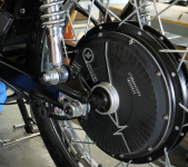
What prevents the axle from slipping out of dropouts?

mazzola

1 mW
Joined
May 23, 2023
Messages
18
Location
Austin, TX
For hub motors that don't have any chain attached to it, what prevents the axle from slipping out the back or forward whenever the bike accelerates? Looking at other builds it seems like slippage is possible. Is it just the pinching of the axle by the swingarm/axle bolt that prevents slippage in this example?

Screenshot 2023-06-17 at 12.41.36 PM.png

Or is a torque arm supposed to prevent slippage? While I see how this example below would prevent the wheel from totally flying off, it still seems like there's some slippage that could happen where the torque arm is bolted to the swingarm which has a slot to move around in.

Screenshot 2023-06-17 at 12.41.00 PM.png
 
You are right, slippage is more than possible. There is more than one way to approach the problem, it depends on how powerful your motor is and what kind of swingarm you have to work with, as well as the materials and skillset you have at your disposal.

Browse this thread for some suggestions to get you thinking.
 
I've purchased three commercial ebikes, All were alloy frames and rear motors "rated" for 500W, The drop outs are fairly beefy, and they don't use torque arms, but they all used torque washers that fit snugly in the dropouts. Axles are your typical 12x10mm.

On my DIY conversions, I'll use torque arms, because the dropouts are rarely as beefy as what commercial frames use.
 
For hub motors that don't have any chain attached to it, what prevents the axle from slipping out the back or forward whenever the bike accelerates? Looking at other builds it seems like slippage is possible. Is it just the pinching of the axle by the swingarm/axle bolt that prevents slippage in this example?
Pinching torque plates securely bolted to the swingarm (or welded to it) are your best bet.

Designed correctly to parallel-clamp the dropout faces to the axle flats over as much of the surface area of the flats as possible, the axle is going nowhere, even without any other axle hardware (nuts, etc). ;)
 
Okay, so similar to a bicycle wheel, it's the tension created by pinching the dropout faces against the axle flats. I wasn't sure if that tension would be enough for more powerful applications like an e-motorcycle. Let me know if this hand-wavy physics makes sense or if I'm missing something.

Looking at my Honda CB550 manual on p. 2 it says to tighten the 20mm rear axle nut to 98Nm which would create a clamping force of:

F = T/ K * D

Where:
T = tightening torque
K = friction coefficient
D = bolt diameter

which works out to 24,500N of clamping force versus a bicycle's quickrelease skewer's 500kg/4,900N (according to this thread). But this doesn't make sense that the clamping force is only 5x given that the mass of a motorcycle wheel is probably 6x that of a bicycle wheel and the acceleration of a motorcycle is maybe 3x(?) or more than a bicycle. So I'd expect a clamping force that was 18x that of a bicycle to account for the extra mass and acceleration.

But ultimately I defer to your experience and the reality of the builds mentioned above which seem to work just fine :)
 
Don't these hub motors try to twist themselves out, thus the whole big deal about torque arms, which resist the twisting motion. I don't think the main force is pushing directly out of the drop out. Consider the difference between rolling your wheel on the ground vs. locking it up and dragging it across the ground. It's the same sort of thing for these flattened axles, isn't it?
 
Don't these hub motors try to twist themselves out
Yeah the twisting motion is definitely an issue and solved with torque arms like you said. I was more concerned about the translational motion that I'm imagining happens whenever the vehicle accelerates and decelerates due to inertia. For example, when the vehicle is at rest and the rear wheel starts moving forward, isn't there a translational force on the axle that needs to be transferred to push the rest of the vehicle forward?
 
Okay, so similar to a bicycle wheel, it's the tension created by pinching the dropout faces against the axle flats.
Based on your description of the math and manual statements, I'm not sure if you're describing the same thing that pinching torque plates / dropouts do.

They clamp onto the axle flats themselves, preventing the axle from spinning or moving in any direction, without any other axle hardware at all required. (no axle nuts, etc).

Bicycle dropouts get their inboard faces pressed against the axle *shoulders* of bicycle wheels by the axle nuts. This prevents the axle from shifting around in the dropouts, but is not intended to prevent it from rotating (because that in itself is not important to a bicycle or motorcycle wheel (with two exceptions, an IGH or a brake hub, if those don't have integral torque arms) , while it *is VERY* important to a typically-designed hubmotor wheel with axle flats and no integral torque arm)

They're two completely different directions of force and methods of attachment, designed to do different things.

So...I'm suggesting you not depend on the axle nut and inboard dropout faces, and use the pinching dropouts, which you can find examples of in the Torque Arm Picture thread, or at the present end of my SB Cruiser trike thread, etc. You can still use your nuts if you prefer, but if the pinching part is designed and installed correctly, it'll be secure without them. ;)

I was more concerned about the translational motion that I'm imagining happens whenever the vehicle accelerates and decelerates due to inertia. For example, when the vehicle is at rest and the rear wheel starts moving forward, isn't there a translational force on the axle that needs to be transferred to push the rest of the vehicle forward?
Yes, and that is what the torque arm does--transfers the motor's rotation to the frame via the tiny itsy bitsy axle flat surface area that contacts the torque arm's interface.

The pinching torque plate or dropout does the same job, and can be designed with a much larger surface area in contact with that tiny axle flat area because it can replace the nut (and potentially the entire dropout of the frame, so that *all* of the axle length can be clamped to if you find that necessary for the torque a particular system produces).
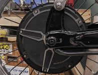
 
Last edited:
I wondered about this very thing and it seems to me that, by default, the forward momentum keeps the axle mostly pressed against the fork, so the pinched clamp has an easier job keeping it from vibrating and wearing loose. The pinch would do most of the work if the cutout was forward facing in the case of reverse or FWD .
 
I wondered about this very thing and it seems to me that, by default, the forward momentum keeps the axle mostly pressed against the fork, so the pinched clamp has an easier job keeping it from vibrating and wearing loose. The pinch would do most of the work if the cutout was forward facing in the case of reverse or FWD .
If you are using a pinching / clamping dropout, and it is correctly designed, made, and installed, none of the forces against the wheel itself will make any difference to the axle's security. It will do all the work of keeping the axle in place and prevent it's rotation.

If those forces do make a difference, then the dropout, clamp, etc. is not designed / made / installed correctly for the situation.
 
The acceleration and using the e-brake (high/low) function, rotates the hub motors axle back and forth, loosening the axle bolt over time if you do not have a properly fit, and tight torque arm

Sometimes when I was in a pinch I'd have only one torque arm installed, I could sometimes feel the bike accelerate more to one side on a rear hub setup. If it got worse, it usually meant a loose axle nut on the non ta side or my custom steel ta's were going out of precise'ness. I'd rather have the ta fail then have a damaged axle. So for about a month I'd carry around a axle nut wrench, until I made the 2nd ta out of steel, and hose clamps.

The ta's to buy are the Grin tech ones.
 
Back
Top