Why are my cells in parallel when not connected in parallel?

Offroader

1 MW
Joined
Sep 8, 2013
Messages
2,630
Location
USA
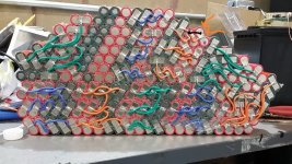
I built this pack and never connected the cells in parallel. Every two cells are connected in series to another 2 cells randomly in the next parallel group.

When I check ohms between any cell in that parallel group (or the next parallel group connected with the series wires), it reads like 5-10 ohms. I'll get a negative ohms if I reverse the leads on the same cells. SO for example I'll get 6.5 ohms between two cells and if I reverse the leads I get a -4.7 ohms. I can also check voltage between any cell in the parallel group.

Not sure what is going on here. Anyone have an idea why the cells have continuity between them without having the parallel connections? Why does it read negative ohms when reversing the leads?

What also may seem very odd is I tried charging a single cell as shown in the picture with the orange arrows. It is connected only with the same tab on only the negative side as the other side the tab is connected to a different cell (basically two cells have the same nickel tab only on the negative side and on the positive the tab is connected to a different cell as shown with the black line on the other side). It was very slow charging the single cell and that is when I noticed it charging other cells in the group.
What happened was it started to charge the cells next to it (maybe others but I didn't test them all), but it also seem like other cells got discharged?????, I discharged the cell back and everything went back to the same voltages.

Thanks if anyone has an idea about what is going on here.

 
Offroader said:
When I check ohms between any cell
Are you measuring only from one end of a wire (or other conductor) to another? This is the only way to get a valid ohms reading.

Or from one cell to another?

If you measure anything with a voltage potential between them, you won't get a valid ohms reading, because the meter is using it's own voltage source to determine the ohms. Any other voltage source will interfere with (opposing or adding to) the voltage from the meter and cause invalid readings.


in that parallel group (or the next parallel group connected with the series wires), it reads like 5-10 ohms.

Within any parallel group, you should get an effectively zero ohms reading. If you don't, they aren't actually fully paralleled, because there is resistance between them, and thus a voltage potential (higher the more current that flows, and vice-versa (more current the higher the voltage potential is).


I can also check voltage between any cell in the parallel group.

The voltages should be identical between any paralleled cells. If they are not, then they are not fully paralleled...see above.


What also may seem very odd is I tried charging a single cell as shown in the picture with the orange arrows.
I can't see a picture; I see when I quoted your post it's on photobucket. If you upload it directly to the forum I could see it.
It was very slow charging the single cell and that is when I noticed it charging other cells in the group.
If they are paralleled, then they are all going to charge at the same time, and at about the same rate, varying only with internal resistance and interconnect resistance.


What happened was it started to charge the cells next to it (maybe others but I didn't test them all), but it also seem like other cells got discharged?????, I noticed some cells dropped in voltage in the parallel group. I discharged the cell back and everything went back to the same voltages but I could have sworn some cells lowered in volts in the parallel group.

Sounds like the pack is not wired the way you think it is? Paralleled cells will all charge at the same time, though possibly at different rates depending on their internal resistance, and the interconnection resistances.


The only kind of cells that will *appear* to be discharging (dropping in voltage) when ohter cells in parallel appear to be charging (increasing in voltage) are NiMH and NiCd, once they reach the delta-V point (full state), as the full ones drop in votlage and become very hot as the charge dissipates as heat.

That's why it is bad to ever parallel that kind, because the ones still charging will keep pouring current into the already full ones, which will get hotter and hotter and hotter until they probably explode or catch fire.
 
Can you really not see the battery image. I changed the link, I can see it fine.

Actually the cells are not connected in parallel in the group. I just call them a parallel group. They are basically a bunch of cells connected in series that are tied together at the end with the main battery wires.

I guess I would have to remove where all the cells are tied together at the end to see if this is the reason why I am getting continuity between the different cells in the same parallel group (but cells are not physically in parallel as shown in the battery photo, not sure how I would call that group of cells)

This is all very confusing because of the way I built the pack.

If you look at my pack you can see that the each two cells are connected to two other cells in the next cell group. There are no parallel connections made (well maybe two cells share the same tab but that is it, and on the other side of the pack those two cells may share different tabs with other cells).
 
Offroader said:
Can you really not see the battery image. I changed the link, I can see it fine.
I cannot see any Photobucket pictures, because the site tries to use scripts that wont work on my ancient browser (at least, it seems to be why). I can't view them on PB site directly, either. Some parts of their pages load, most do not.

I can always see pics attached to the forum itself.

I wish everyone would just attach the images directly, because anyone that can access the forum to read the post can also download the images, even if their browser does not directly support viewing them for whatever reason. And because offsite links go dead a lot, but stuff on the forum itself generally sticks around permanently, though there have been a couple of times images were lost it wasnt' nearly as bad as all the offsite stuff that's just vanished over the years.


Actually the cells are not connected in parallel in the group. I just call them a parallel group. They are basically a bunch of cells connected in series that are tied together at the end with the main battery wires.
Ah, then they are not parallel groups at all, and cannot have resistance measured between them because of the voltage on the cells.

You can measure the voltages between them, and calculate the resistance based on current flow at that voltage, or vice-versa, but directly measuring the resistance with a typical DC ohmmeter wont' work, AFAIK.

The term "parallel group" is very confusing in this situation, because it does not apply.


I guess I would have to remove where all the cells are tied together at the end to see if this is the reason why I am getting continuity between the different cells in the same parallel group (but cells are not physically in parallel as shown in the battery photo, not sure how I would call that group of cells)
No, you cannot measure continuity at all, becuase of the voltage on the cells. The way the ohm meter works it cannot be done. (you may even damage the meter trying to do it, if it is not protected against this).


If you look at my pack you can see that the each two cells are connected to two other cells in the next cell group. There are no parallel connections made (well maybe two cells share the same tab but that is it, and on the other side of the pack those two cells may share different tabs with other cells).

I'd need to see the pictures of the pack, or you'd have to draw a diagram, but it doesnt' sound like it's made the way any typical pack would be, so I'm not sure what your results would actually be for any particular measurement or cell-level charge or discharge action.

But I think there is still an explanation, if you see the last paragraph below the
*****************


Normally, either each group of cells is

--a series group of cells, connected at the most positive end to the most positive end of all other such groups, and the most negative end of it to the most negative end of all other such groups, and those are the pack's positive and negative outputs.

or

--a parallel group of cells, connected with all the postives together, and all the negatives together, with the negative of each group connected to the positive of the next more negative group of cells, and the positive of each group connected to the negative of the next more positive group of cells, except for the two end groups whose unconnected ends are the pack's positive and negative outputs.

Both of those give very predictable results, becuase with the second, all cells in any parallel group will be the same voltage, though each group can be a different voltage, totalling up to whatever the full-charge voltage is.

with the second, while no individual cells in any series group will be the same voltage as any other cell, the total voltage of any group will all be the same as every other group. As long as all cells are good, and the same IR and capacity, this won't hurt anything, or affect performance. If they're not, though, then you get different voltages on different cells, and you have no way to use a single BMS to keep them balanced or monitor HVC or LVC, and it's possible for stuff (if unmonitored) to get out of balance, potentially badly enough to cause problems.

*****************

So if you attempt to fix series strings by charging single cells up, then that whole string is now a higher voltage than the other strings, and discharges into the other strings.

This means that:

A) The individual cells in that string *other than the one you are charging* are now all discharging,

and

B) all the cells in all the other strings are now charging.
 
I dont know what you have built, ( it might help if you tell us what you think it should be ..how many series cells , how many parallel...). And i dont know what you are measuring or using to measure with..BUT ,..it is not possible to have a negative ohms reading..no such state exists !
You have built something you dont understand, so be careful attempting to charge or connect anything to it .
 
I agree it is hard to understand what I am getting at. Tomorrow I'll try and put something together to try and make this more understandable.
 
Based on how you have the battery built (at least, as described), the quote below (from the end of my previous post) is almost certainly the reason you would see other cells in other series strings change voltage when you are charging a single cell in a different string.


while no individual cells in any series group will be the same voltage as any other cell, the total voltage of any group will all be the same as every other group.
<snip>

So if you attempt to fix series strings by charging single cells up, then that whole string is now a higher voltage than the other strings, and discharges into the other strings.

This means that:

A) The individual cells in that string *other than the one you are charging* are now all discharging,

and

B) all the cells in all the other strings are now charging.
 
Ahh i see what you are saying, I'm going to have to rethink this again. Feel stupid now :oops:

Because when I charged that one cell, I could have sworn other cells actually fell in voltage. But like you say this would happen. Those cells were probably in the same series string but in a different series group. Because the voltage had to even out.

I actually wrote that I noticed some cells seemed to have discharged in my original post but edited it out because it didn't make sense and I thought I made a mistake looking at the cell voltages. I also didn't really remember exactly where I noticed the lower voltage cells as I was moving around my large pack.

But it makes sense because the other cells in the same series group were increasing in voltage, although less voltage then the cell I was charging.

I feel really stupid because I know the concepts very well I just didn't think it through enough to see how it all played out, and how having the main battery wires connecting all the different series strings would change things. I always had my cells in a series group connected in parallel so never had to deal with these issues.

The question still remains on why does my ohm meter read continuity between cells in the same series group and same polarity side, like they were connected in parallel.

In the picture that I attached you can see that the tabs are not connecting in prallel. Yet if I touch my Fluke probes on different tabs in the same group I will get about 3-24 ohms depending on the group.
 

Attachments

  • battery build.jpg
    battery build.jpg
    157.2 KB · Views: 1,122
Offroader said:
The question still remains on why does my ohm meter read continuity between cells in the same series group and same polarity side, like they were connected in parallel.
I'm not sure how else to say this, so I'll just say it basically the same way again:

You can't use an ohm meter to measure anything in there, because the voltage on the cells invalidates any reading the meter tries to make by using it's own voltage.

No reading will be valid unless it is *only* directly on a single conductor with NO cells in the path.

If there are ANY cells in the path it will not read correctly, and can actually damage your meter if it is not designed to protect against that.

If you were measuring just the conductors, and not the cells, you woudln't get the readings you do.

Regarding the picture...I can't figure out what I am looking at, to see what is in series and what is in parallel.

I do see a bunch of cells that aren't even connected to anything at all, which doesn't make any sense--they are just a bunch of wasted weight and space like that. :?

I think you'd have to draw out on it which cells are part of what strings, and then how they are connected, to figure out what you've actually built.
 
Yeah,, what is up with that block of cells in the middle? In the pic, which may not be how it is now,, they are not connected at all.

A chunk of cells that size,, and obviously different types and sizes, I'd have made it in 12v chunks, since IMO, different parts of it will have different lifespans.
 
My fault, the pack in that picture wasn't complete 100%, and my pack is now wrapped in kapton tape so you can't see the connections as clearly. I finally connected those last two series groups like the others.

I guess the Fluke is reading incorrect values because of the DC electric.


Attachments

  • battery 2.jpg
    battery 2.jpg
    172.6 KB · Views: 1,083
Offroader said:
My fault, the pack in that picture wasn't complete 100%,
Ah. These are the kind of details it's important to make note of, to avoid confusing those trying to help (and keeping them from giving you confusing advice). ;)

I'd still highly recommend drawing out exactly how that pack is *really* connected, with straight lines of cells, verified by manually tracing out each connection and marking it as such on the pack as you go (sharpie, post-its, tape, chalk, etc), to be sure you don't leave any out or do any twice.

Not only will it help you see exactly how things are wired up and thus how current should flow and voltages be measured / measurable, it'll also be useful when troubleshooting it later, either on your own or when getting help from others. :)

In a pack that's not a straight-up block configuration, it can be very hard to see exactly what the groups and paths are, depending on how it is laid out. It's especially hard when you come back to it after some time has passed and you might not remember exactly what was done, and having to trace it all out again every time gets to be a PITA.

I've fixed a number of battery packs made of small cells, and only a few were simple layouts. :/ The rest required drawing them out to be sure I understood which cells were in which groups and in which order, and some were very confusing because of the shape they made out of the cells.


Offroader said:
I guess the Fluke is reading incorrect values because of the DC electric.
Yeah, unfortunately you just can't use ohmmeter functions across cells / voltage sources (between them, yes, across them, no). :(
 
Yes I agree, actually it was smart that I used different color wires for each series connection. This way i can more easily see trace exactly where each groups are.

I can imagine if it was just all nickel tabs connecting everything, I wouldn't be able to easily see the series groups.
 
Offroader said:
Yes I agree, actually it was smart that I used different color wires for each series connection.
That is yet another detail that would've helped people understand how it was wired.
 
Man!! This pack is a nightmare to look at. Power sharing is bad. The shape is bad because only the clue is holding the cells. When the cells are warming up the glue melt and the vibration will do the rest of the damage...

I know you have put lots of time in this

I'm only saying that for your safety. I don't like talking about other people stuff (experiences) but I think somebody as to say something...

Best Luck!
 
What do you mean by power sharing?

It was also a worry that the pack is only held with glue, but it is very solid. I used some good hot glue which is so strong that it would rip the cell covering off before the glue gave out.

The reason why my pack is also safe is that it is held so firmly in place in my narrow frame that the pack has almost no movement. The side covers squeeze the foam sheets tightly from both sides squeezing the pack tightly. The closed cell foam surrounds the rest of the pack. Battery needs to be pushed out hard to remove it, and this is after months of bike use also.

I agree with you in that if someone else was to build a similar pack I would worry about their pack because I would doubt their workmanship. I spent lots of time to make sure every soldered wire was heated high enough and pushed firmly onto the tabs with a lot of force and flattened down. Basically every soldered connection is perfect and I was very obsessive compulsive about this. If I felt I didn't heat the solder high enough or the wire wasn't flat and spread out enough on the nickel tab, I would redo it.

If anyone else would have done this they would probably have lots of bad solder connections and having the wires pulling off. So you are right in that I wouldn't recommend this pack built unless you are very careful and experienced with building it.

Pack voltages so far are all within .003-.005 of each other and I didn't parallel the cells after using it for over 5 months.


Power sharing: making sure the connection in series have the same or close to the same length so resistance in the wires is minimized. If you have the same length or same resistance, you have more chance of keeping the cells balance and age evenly.

For high power systems is very important to take in consideration how the pack is breathing and what cells suffer more from heat generated by the discharge...
The cells in the middle suffer ways more and that should be a big consideration in the design...

BTW after building many battery pack for myself and customers I can tell you that vibration, hot glue and heat from the cells is a known scenario for disaster.

Sorry I'll love to explain more but I’m French so it's painful for me to write long sentences...

I know you work hard making this thing that the raison I took the time to say something about it.

Good Luck
 
Figured that pic was not how the pack is today. At some point in the pack,, you do have cells paralleled. they might be 4.2v cells,, or 72v cells, in effect after series connection.

If I am not wrong,,, you have 2p then whatever s in series. and several of those series packs connected parallel?

Wow,, kind of a nightmare to monitor cell voltage of that, IMO. Huge pack, hard to monitor for balance,, what fun.

Correct me if I'm wrong,, there seems to be a lot we need to know to understand your pack, or even what your packs problem actually is.
 
Actually power sharing in the pack is perfect and the reason I used the wires. Because the pack was not square or rectangular, the wires allow perfect power sharing. Each series connection uses the same exact wire length between the two parallel groups. This would have been impossible to build a pack like mine without using wires.

Right now I didn't parallel the cells yet some some are in 2p or 1p, depending on how they are connected on the other side of the pack. They are only tied in parallel at the very ends of the pack.

I don't have any problems at all with the pack except I was stupid to think I could cycle a single cell while still connected in parallel at the ends of the pack. :oops: I wanted to capacity check a single cell to check capacity loss.

The voltages are still near perfect between all the cells after 5 months of use, still within .003 of each other and that was about what they were when I first put them in.
 
Back
Top