MTH07
10 µW
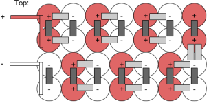
I am planning a 14s3p battery build for an ebike, and would like to make it in an "out and back" layout with 7 sets of parallel cells in a row with a copper bus bar connection to another 7 sets of parallel cells. The image below is a 14s2p configuration that I found that is essentailly what I want to do except in 3p rather than 2p (credit roadrich on electricbike.com; ignore the connection methods, etc. I am including that diagram just to show how I am thinking about laying out the cells):

My concern is a short or an arc at the end where the positive and negative leads are given the short distance between the tops of the batteries and nickel strip, particularly close to the end where the leads attach where there is a bigger difference in potential. Is this an inherently bad layout, or could that be remedied by using a divider between the two rows of parallel cells (e.g rigid plastic, foam rubber, kapton tape). This configuration would work much better in the space I would like to fit the battery, but if it isn't a good idea, I will just go with the typical 14s in a row and figure out a different mounting option. TIA for any suggestions or thoughts you might have.

My concern is a short or an arc at the end where the positive and negative leads are given the short distance between the tops of the batteries and nickel strip, particularly close to the end where the leads attach where there is a bigger difference in potential. Is this an inherently bad layout, or could that be remedied by using a divider between the two rows of parallel cells (e.g rigid plastic, foam rubber, kapton tape). This configuration would work much better in the space I would like to fit the battery, but if it isn't a good idea, I will just go with the typical 14s in a row and figure out a different mounting option. TIA for any suggestions or thoughts you might have.
Last edited:

