Wiring for Torque Sensor on Cycle Analyst

spooknik

1 mW
Joined
Oct 11, 2022
Messages
13
Hello everyone

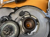
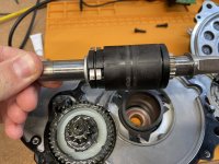
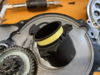
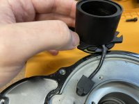
I am installing a Baserunner and Cycle Analyst on my eBike. My eBike is mid motor and has a torque sensor on the spindle (see pictures attached). The connecter has 7 pins but only 5 are used. The pinout on the controller looks like this, I mapped it to the connector.

IMG_1349.jpegScreenshot 2022-11-03 194915.png

Any idea how these pins translate over to the Cycle Analyst pins?

image.png

The Pins on the controller / Torque sensor are:
GND
VCC5V
AD1
TA1
TA2

Pins on Cycle Analyst are:
GND
10V (Step down to 5V)
DIR
RPM
TRQ

The GND and VCC are obvious but I'm not sure about the other pins. I think on the CA i'd only end up using the TRQ pin but i'm not sure. Any input is appreciated 8)
 

Attachments

  • IMG_1350.jpeg
    IMG_1350.jpeg
    962.7 KB · Views: 196
  • IMG_1351.jpeg
    IMG_1351.jpeg
    644.6 KB · Views: 196
  • IMG_1352.jpeg
    IMG_1352.jpeg
    576 KB · Views: 196
  • IMG_1353.jpeg
    IMG_1353.jpeg
    747.7 KB · Views: 196
To find out which pins are which, you'll have to apply power to the sensor and use a voltmeter to see what the outputs are in-use (you'll need the torque-sense-output voltage range numbers to calibrate the sensor in the CA anyway).

Depending on the specific design of the torque sensor, you're going to have to apply a torque load between the chain's top run and the pedal chainring, or across the BB from one pedal to the other. The simplest way is by just riding it, and since you have to monitor voltages while riding this should be done where you won't crash into anything or be crashed into. ;)

If necessary you can put the bike upside down and lock the rear brake so the wheel can't move, then apply hand-pressure to the pedals so it tensions the top run of the chainline, from either the left or right pedal; it's not as "real" a situation but it's more controllable.

If the sensor is powered by 5v, then you can supply that either from the CA or the controller you're replacing the original with, or even a separate source.

Once that's applied, set your voltmeter to 20VDC, and place the black lead on GND, and the red lead first on AD1. Note down the voltage you get with no load on the pedals. Place torque on the sensor via whatever method you've decided on, and note the voltage range you get from zero load to full load on the pedals.

Move the red lead to TA1, and repeat. Same for TA2.

If you only get a smoothly changing voltage on AD1, it's probably the torque sensor output, and the other two are probably the PAS / cadence sensor output.

If you rode the bike to do the test, you'll also have gotten pulses on at least one pin, probably TA1 or TA2.

If you used a locked rear wheel to do the test, unlock the wheel and retest the ones that had only a static unchanging voltage, and you'll probably get pulses on one of them now.

The one with the pulses is the PAS/cadence sensor.

Move the pedals backwards, and the one without pulses will probably change voltage now, where it didn't before. If so, that's DIR.

If you get other results than these, post what you get and we'll try to figure out what it might be.
 
Thanks once again amberwolf, helpful write up. I'll give it a go this weekend :)
 
Alright, so I did a bit of testing

AD1 is indeed the torque sensor. No load voltage is 0.48V and when you put load on it, it will smoothly increase, let off and it decreases. Only saw it up around 2V but i'm testing it on my workbench stationary, i'll do a test ride tomorrow with the multimeter rigged up somehow. I'm guessing it peaks at around 5V, but I want to test to be sure.

AD1 then should connect to Trq on CA.

TA1 and TA2 appear to be doing the same thing. They are some kind of PAS (maybe position?) sensor that either reads 0V or 5V depending on where the pedals are. If you move the pedal it's either in a "zone" where it reads 0V or 5V. I counted there are 24 positions where 5V gets activated. At pedaling speed the voltage is around 2.5V The only difference between TA1 and TA2 is that when TA1 reads 5V, TA2 reads 0V and vice versa. (Let me know if that makes sense or not, I can make a video, probably a lot easy to understand than words)

I'm not sure if TA1 and TA2 are useful for CA or where they would connect. :?
 
spooknik said:
TA1 and TA2 appear to be doing the same thing. They are some kind of PAS (maybe position?) sensor that either reads 0V or 5V depending on where the pedals are. If you move the pedal it's either in a "zone" where it reads 0V or 5V. I counted there are 24 positions where 5V gets activated. At pedaling speed the voltage is around 2.5V The only difference between TA1 and TA2 is that when TA1 reads 5V, TA2 reads 0V and vice versa. (Let me know if that makes sense or not, I can make a video, probably a lot easy to understand than words)

I'm not sure if TA1 and TA2 are useful for CA or where they would connect. :?
As noted previously, the PAS sensor (cadence sensor) will output pulses as the pedals rotate, and connects to the PAS pin on the CA. The number of pulses per rotation is the "poles" setting in the CA.

There are various kinds (there's a page about PAS sensors on ebikes.ca that shows some detail about it), but your sounds like a quadrature type, so you would connect the other pin to the DIR pin on the CA (same as if it was a direction wire that only read 0v one way and 5v the other).

Then choose one of the two-wire torque sensor options in the CA and customize from there, or start with the custom sensor option and set it up as needed.

If it only works when pedalling backwards, change DIR=5V to 0V, or vice-versa.
 
Thanks, that makes sense now! I didn't realized those were as the pulses you were talking about :lol:

A follow up question regarding wiring:

I am using the Baserunner L_10 controller and the motor connector has a pin for the NTC temp sensor. But the CA also has a spot from the temp sensor. Which one is most correct to connect to? It would be easier and less wiring to connect it to the baserunner because it's closest to the motor.
 
Depends on what you want to happen.

If you want the BR to directly do thermal rollback of power, which you can't really change or override during a ride (unless you have a portable way to connect to it and program it), then that's where the sensor goes.

If you want the CA to just send less throttle as it gets hotter, then the sensor goes to it. This can be edited onscreen during a ride if necessary for fine tuning, and if you absolutely had to you could override it (at the risk of damage).
 
Back
Top