XLD Brainpower LSD149 - Remove LVC

c111jp

10 mW
Joined
Feb 25, 2023
Messages
25
Location
Tokyo
I've bought a XLD Brainpower LSD149 controller. On the case, lower voltage is indicated as 42V for 48V battery. That's 3.2v per cell. I have Samsung 50E that can go safely lower than that so I want to lower or ideally remove Low Voltage Cut out entirely. I also have Bluetooth BMS so I can control cut-out there.

How would one achieve so?
Seems like to lower it, one would have to play with resistors on the voltage divider.
I've heard this would also affect regen. In which way exactly would the regen be affected?

Another way I've heard of to completely disable LVC is by shorting ADC pin to 3.3V. Does anyone know more about that? Would that also affect regen? Would really prefer not to fry controller the same minute it arrives lol.

Also if anyone knows any means of how to control / program these, that would be great alternative route.
Thanks!
 
I posted this in your other thread, but since you made a whole new one for this question I'll just copy it here, too.

Disabling LVC might be possible, but is not generally a good idea (see the post below the first quote below for battery specific reasons).

It's not just there to protect the battery, but also the controller. If battery drops too far, the LVPS in the controller may not be able to convert battery voltage to the correct voltages to run the rest of the controller properly, or it may stress the parts in the LVPS depending on it's design.

If it's low enough, it also can't generate the full voltage to drive the FET gate drivers, so the FETs aren't being fully turned on or off, and/or not as fast as they should, so they heat up and can fail.

Anyway, got this controller in the meantime since it was locally available while I find a "perfect" controller. It's XLD Brainpower LSD149. If anyone have any tips for those, they are of course welcome.

There are some threads for XunLida / Brainpower controllers with some info, if you poke around.


Seems like it should be fine out of the box but one thing I'm worried about is Low Voltage Cutout. It's written as 42V for 48V on the controller. I have 50E cells which have 2.5 voltage cutout, I wouldn't go that low but they are fine up to about 2.8 volts which is 36.4 v so I would be leaving quite a bit of capacity on the table.
Ideally I would remove LVC all together but apparently this will affect regen.
You don't really want to run cells down that far, if you want to keep the battery unstressed and long-lasting. 3.0-3.2v / cell is the lowest I would use for a controller LVC--they're set this way to prevent potential cell damage...especially since almost no ebike battery is made of matched cells, so they don't stay balanced, and you can have some cells that are much lower than others. If you use a controller LVC (that can't actually know how low the cells are) that's at or near the actual per-cell-level LVC, then you can damage cells that are below that average voltage. Such damage is cumulative, will shorten the pack life, and if severe enough can create a fire risk.

If you are running a typical BMS on the pack, then that will help do cell-level protection, but the BMS LVC is an emergency shutdown, cutting all power to save the cells from damage. You don't use that for everyday protection, so the controller LVC is set higher on purpose, to use as everyday protection. If there is no BMS, then the controller LVC is your only protection, so setting it higher is even more important.

So for a 13s pack (48v) you'd usually use a 41-43v controller LVC. For a 14s pack (52v) a 44-46v LVC.

There is not all that much actual capacity in most cells below 3v, and some not even below 3.2v at higher currents. See the testing charts here for this cell:
for some info on that; first chart copied below:
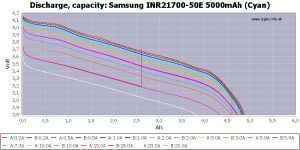
1682311594277.png
 
Last edited:
Thanks, all great info here. Looking at it a bit better, 2.8 is definitely pushing it but 3.0 should be fine for emergency (vs 3.2 now). Just to be clear, cells will hardly ever see less than 3.3v and more than 3.9v in my day to day usage but was looking into removing LVC for "emergency" situation when stuck somewhere. Would be pulling very low current from cells at that low voltage in any case. I'm trying to setup my bluetooth BMS's SOC calibration through those graphs assuming average 2A that I'm pulling from the cell most of the time and I want 0% to be actual 0% but it's hard to determine what would that be.

In any case, I've gave up on tampering with it for now and will see how unpractical it will be in real life usage. So far in few days commute I've never even come close to hitting low voltage cutout.

As for matched and balanced cells, after my thread on cells recommendation, I've pushed UPP and specifically asked multiple times to assemble pack out of close matched cells (voltage, internal resistance etc) and they agreed. Looking at cell groups through my bluetooth BMS, while idle, the difference is usually at most 0.005 - 0.008. The highest difference I've seen was while charging / discharging and this was 0.010 but most of the time it's in the 0.007 range. I think this is pretty well balanced unless the app is lying somehow. Balancing function never even kicks in since lowest I can set it is 0.01 difference.
 
Wtihin a few thousandths of a volt is pretty well balanced, especially if they are like that under max discharge load or during the highest current phase of charging (which will show mismatching much better than a static voltage test), but remember that this is not the same as well matched. Balance is just what voltage the cells are at at any one instant, while matching is the resistance, capacity, etc. properties of the cells that cause them to be at any specific voltage under any specific load vs state of charge.
 
Back
Top