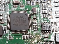
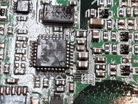
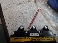
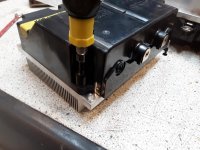
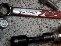
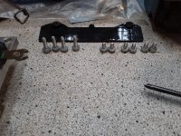
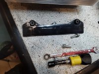
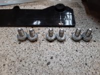
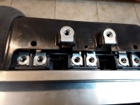
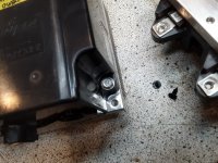
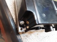
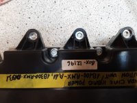
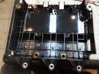
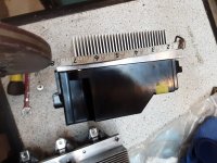
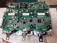
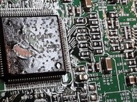
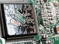
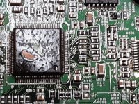
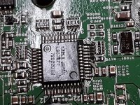
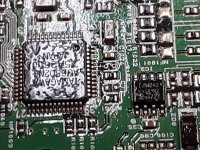
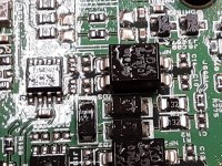
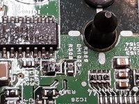
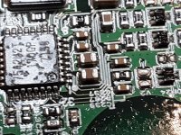
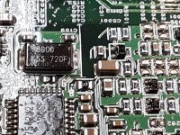
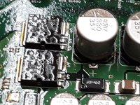
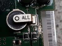
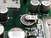
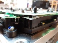
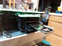
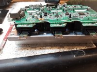
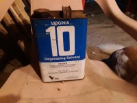
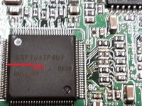
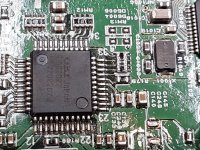
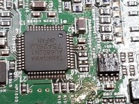
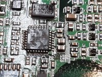
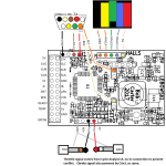
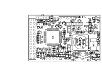
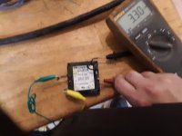
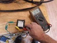
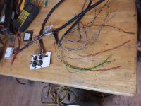
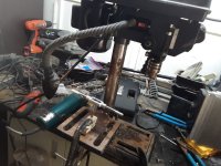
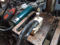
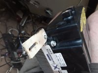
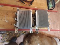
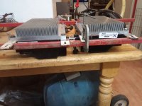
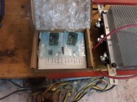
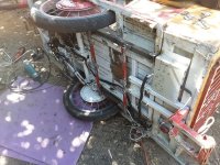
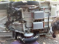
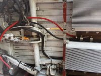
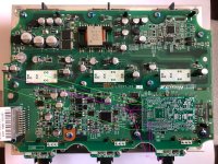
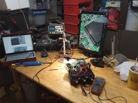
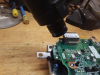
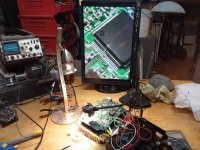
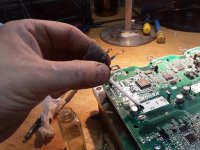
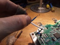
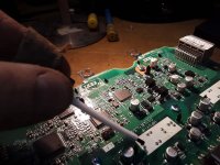
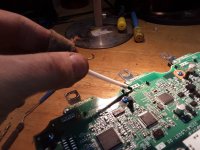
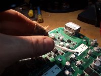
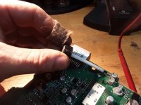
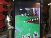
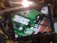
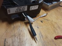
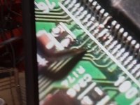
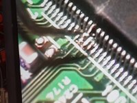
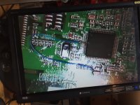
"Zombified" meaning one that has had it's brain disabled...I suppose lobotomized would apply except that in this case the plan is not to actually *remove* anything from the IMA, just disable the main CPU by holding it in "reset", per this thread:

 endless-sphere.com
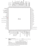
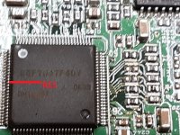
once I find enough information to locate the reset pin on the IMA's CPU. EDIT: information located, placed in post linked below.
Thread links for what the heck the Lebowski brain board actually is:
The BobC brainboard thread:
The main Lebowski Firmware / chip / manual thread:
The opensource-release / explanation thread:
Some discussion of the project, and what led me here, first. (mostly because I don't yet have the parts to begin the project itself, and much of the upcoming documentation will require having the parts in hand. EDIT: as of last week of April, all the major parts have arrived, and work is in progress, documented below.) If you like, you can skip ahead to the next posts that begin documenting the process (once they're written I'll make an index just below this paragraph).
INDEX:
--Location of Reset Pin on CPU, pinout and other chip documentation
--IMA documentation, Location of Reset Pin on CPU, CPU pinout and other chip documentation (will also include documentation from other IMA projects around the web as I locate them)
--Disassembly, basic dimensions, pics of the insides.
--Brain board wiring and setup, including the 12v DC-DC for running the IMA gate drives, connector pinouts, BobC SMDLebowski board buildup / test instructions & schematic, etc
--enclosure of the brain inside the IMA inverter
--optional mountings, setups, afterthoughts, etc.
--Initial offground testing
--Initial road testing
Base information leading up to the project, and some RAAaannntzzzZZ:
You can skip all the rest below if you like, and just follow the links above to the details of how to do this yourself. (once they're all written--right now some of those links just go to "reserved" posts).
The plan, when complete, is to run the hubmotors that drive SB Cruiser

 www.endless-sphere.com
with a pair of these, because i have yet to find anything affordable with sufficient power *and* customizability / programmability, that also has all the functions I require. Everything I *have* tried has been disappointing in performance or features at best, and extremely frustrating or even destructive, either in operation, setup, support, or in it's failure, at worst.
The main needs I have are:
-- current (torque) throttle control
-- true sinewave commutation (with FOC if possible, but I'm really after the silence)
-- startup from a complete stop by itself, under high mass (inertia) load.
-- sensorless operation available as well as sensored (for the above)
-- sensorless fallback mode for when sensors fail
-- easy-to-implement analog (proportional) electric braking control with a separate analog input just for this (no wierd setup using the throttle to control braking while holding a brake lever that's just a switch)
-- braking capable of bringing the trike to a complete stop
-- braking that will have the same negative torque capability at high speed that it does at low, basically able to (hopefully, but at least almost) skid the wheel at any speed, when max braking input is applied.
-- easy to use setup program and user interface
-- ability to read out existing settings
-- ability to change hvc, lvc, current limits, other behaviors as the design contains/allows
-- good clear documentation on how to use and setup the controller, and what all it's options are and can do and how to use them
-- good support available for when my brain explodes
-- large enough installed userbase to judge usability/reliability/suitability for my purposes from reported problems
-- low enough cost that I don't have to scrimp on everything else for months (or years) to pay for them (cuz I need two, at minimum)
-- no onboard display required to operate it
-- more stuff I can't remember right now
Other things that would be great, but not required:
-- open source design and firmware
-- ability to actually hold the trike in place with active braking force, without mechanical brakes, for some occasional momentary situations
-- ability to dump enough torque into the wheels to smoke the tires (not that I plan to do this, but having that kind of power could be useful under certain circumstances).
Don't worry, the next paragraph, while long and arduous, can be skipped entirely and you won't miss a thing, unless you, too, are frustrated with (advanced and/or reliable) controller options out there.
Everything I have and *haven't* tried is one of the following (see if you can guess which ones these are, but keep them secret so as not to spoil anyone else's fun): Some beefed-up basically "chinese junk" controller (even if some have better parts, the design is still a clone of a clone of a...of a bad design to start with). Some of *those* are even programmable in a limited way, but the better hardware ones seem not to be, generally, with a few exceptions..but even the programmable ones don't do what i want, and can't in most cases due to their designs. An apparently good (not perfect, but good) hardware design, with decent setup options, not hard to understand, but with the most impossibly complicated dance to set it up (enter values in a spreadsheet...copy hexadecimal from that into a terminal program...connect a serial cable to the controller...send the data...reboot it...and oh, you can't ever read the existing settings so you can never know if it *actually* is setup the way you want....), and a realtime status readout in binary that you have to memorize the codes for.... A probably great hardware design, with lots of variants for every need, and probably every feature you could ever want...but impossible to setup without at least several degrees in subjects I'm not even sure what they are, and if you're not an OEM buying thousands of them, the manufacturer is not going to help you, and you *cannot* use it without doing that setup, specific to each and every different system and motor. Some pretty good designs, very programmable, no degree required, but only available for low to medium power from the one reliable place that sells them, and very expensive for that...the higher power versions are even more expensive, and dont' have nearly as easy to use a setup program. Some opensource firmware projects that look pretty decent for their options and programmability...but only work on what amounts to the chinese junk clone designs. Etc.
The only controller I know of that does almost everything I want, that isn't a zillion dollars, or isn't one of the above, is the Lebowski brain...but it doesn't come as a complete controller. Which sucks. Cuz I'd've just bought a pair if anyone offered them in the right power level, if they weren't exorbitantly priced.
So...the best option I have is to take a good reliable powerstage from a good reliable well-designed controller, and cut it away from it's brain, and then wire in the Lebowski brain to tell it what to do and how to do it, in exactly the way I want it to. It's not the option I wanted, but at least it's not as hard as I thought it would be.
DECISIONS, DECISIONS:
The Lebowski powerstage here:

 endless-sphere.com
looks easy enough, but it's cost is rather high (for me), vs using a completely prebuilt (and road-tested, probably for years!) OEM EV powerstage.
I had originally planned to use a single-chip powerstage that was really easy to build, on PCBs designed and provided by Bobc, but didn't have money to buy the parts at the time, and by the time I did, the chips became unobtainable. (well, there are still some places that show they can get them, but the prices are outrageous and require buying an MOQ of more than I could use or sell in a lifetime even if i could afford that many--effectively unobtainable).
I considered a number of other powerstages (see some of the discussion here
Lebowski's motor controller IC, schematic & setup, new v2.A1 )
but they are either too large, too heavy, too expensive, or require more DIY than I'm really capable of these days, especially fully assembling them "from scratch" even with a kit.
So, based on the success of Tomdb over at DIYElectricCar,

 www.diyelectriccar.com
and with the help of several over here:

 endless-sphere.com
to decide which powerstage to use with the Lebowski SMD board designed by Bobc :rip: and built by Kiwifiat,
I went with the Honda IMA Inverter as the best of the available options, for cost and size and ease of use.
These are possibly the lowest-cost OEM EV Inverter that is widely available, at $30-$60 shipped, if you look around hard enough. You can't buy any one of the major parts needed (like the IGBT modules, or the current sensors) for much less than that, if even that. Now, there *are* plenty of people selling them for several times that, up to a few hundred dollars. But unlike the other EV inverters, the IMA inverter does have a few selling them really cheap, and various people on ES, DIYElectricar, etc, have bought and successfully used those without a problem, so they're not duds (so far at least).
The specific version documented in this thread is the
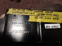
"06-11 Civic Hybrid IMA Power Distribution Module Unit 1B300-RMX-0032"
This link (which will eventually go dead) is for one of these: https://www.ebay.com/itm/06-11-Civi...ution-Module-Unit-1B300-RMX-0032/324436949602
I got mine on ebay from this seller
 www.ebay.com
who gave me a bit more than half-price shipping when i bought two at the same time--not much of a discount, but he didn't have to give any.
  Total cost including shipping and tax was $130.94. More than I wanted to spend (well, I'd rather not spend *any* money), but well worth it if these are as well designed and easy to convert as they appear. They're supposed to arrive early next week, which should be just in time for me to be able to open them up and document them during my upcoming vacation starting the middle of that week.
WHAT'S THAT THAR INVERTER THANG, ANYWAYZ?
Basically the Honda IMA Inverter is the actual controller used to run the IMA motor. So it's equivalent to the controller that's presently running your ebike, etc. The biggest difference is that it doesnt just use a throttle and ebrake input to tell it when and how fast to move the motor, or to stop it, it requires communication (CANbus, IIRC) with the rest of the Honda computers to do this.
So we have to disable the brain that's in there now, that requires this communication that we can't do (there *are* projects on other forums that *do* use it, just that way, but that's not how we roll here... and that's more work than I'm up for).
There's several ways to do that.
Tomdb cut traces on the board and/or removed parts (see his thread linked previously for that), so the brain couldn't operate the powerstage or interfere with another brain's operation of it.
Kiwifiat removed the brain chip (CPU) entirely.
My plan is to follow Jack Bauer's (from DIYElectricCar and OpenInverter) Tesla Model3 hack, which is to find the Reset pin of the CPU chip, and then ground that to hold it in reset mode, which should tristate the I/O pins, effectively disconnecting the brain with a single wire. That's much less physical work, and less risk of inflicting damage on other parts of the inverter, given my various problems (eyesight, random hand numbness, general klutziness, three giant fuzzball monsters that like to stick their slobbery faces in everything I'm working on, etc.).

 endless-sphere.com
This video, starting at 46:01, shows the inverter itself. The rest of the video before that shows disassembly of the IMA unit that the inverter comes from.
[youtube]9Ur_VNd2Lh4[/youtube]
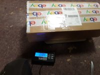
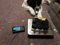
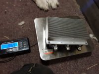
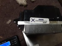
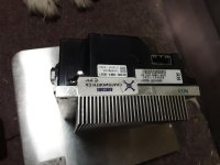
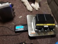
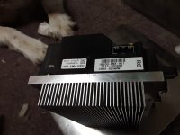
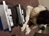
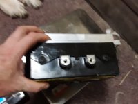
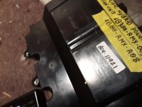
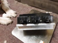
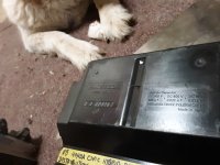
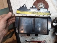
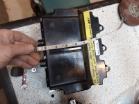
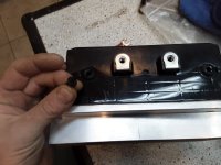
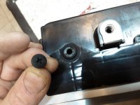
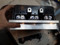
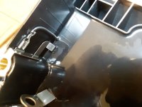
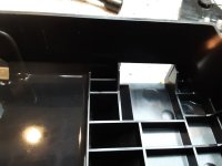
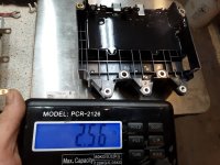
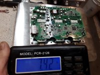
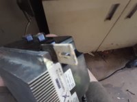
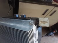
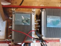
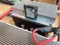
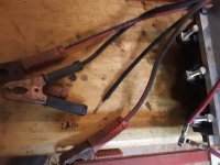
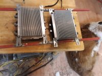
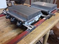
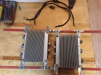
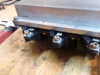
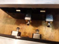
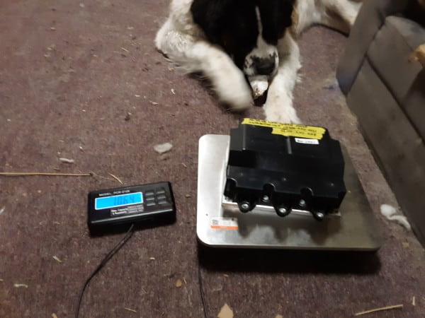
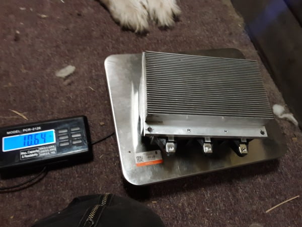
There's plenty of pics of these inverters out there on the web, including internals in Tomdb's DIYEC thread linked above, but I'll post pics of mine when they arrive, with something to show scale. EDIT: As promised, pics, including stuff to show scale (like Yogi, the St Bernard, and the scale itself...Yogi's paws are about big enough to cover the palm of my hand):
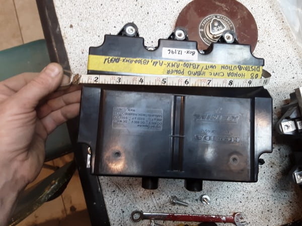
But since you might not know how big any of those are:
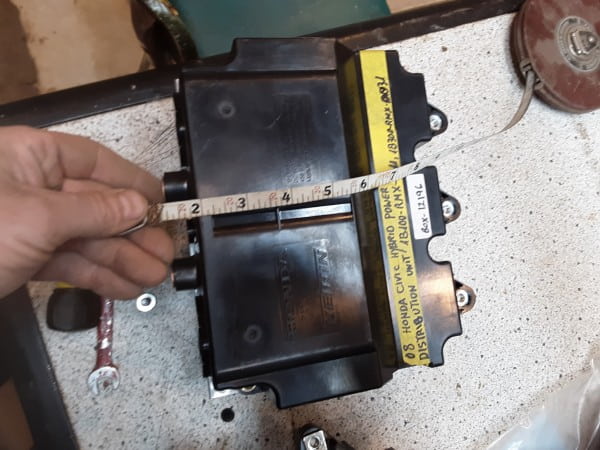
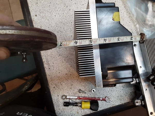
But they're not all that large considering they can handle about 15kw continuously in the Honda Civic hybrid they come from. I don't know what the peak power of those cars is.
As I only need about half that power, and only for a few seconds at startup, at most, I probably won't even need to do anything other than ensure the heatsinks are exposed to airflow under the trike. The only other time I might need more than a few hundred watts from either of them is during braking, if active braking pushes more power thru them than that, and when I'm hauling heavy loads, like the somewhat periodic 300lb-350lb+ grocery trips when I am getting my brother's groceries as well as my own (as his are usually more stuff and heavier stuff, it adds up quickly).
DISADVOLTAGES:
There *is* a disadvantage to using the IMA inverter, for my present system...the IGBTs it uses, vs the FETs the other powerstages I just mentioned, have more voltage drop and thus more wasted heat inside them. For systems over 100v or so, it doens't matter as much because the FETs available for those system have higher resistance and so drop something in the same range, and going even higher the IGBTs will be more efficient than FETs.
However, my system is only 14s2p NMC, so just under 58v fully charged, at present. So there will be more loss in these inverters than the typical controllers used for this system level.
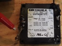
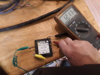
However (again), because the IMA is good for over 150v as used on the Civic itself, I have the option of simply reconfiguring the battery to 28s1p (or seriesing a second 14s2p), without changing anything in the powerstage/brain (except possibly the 12v dc-dc that provides gate drive power, which isn't part of the brain or the powerstage, as it normally came from the Civic's regular 12v system, I believe. In my case a small Vicor brick I have laying around will provide this; only a few hundred mA should be needed as I understand it). I'd have to change other stuff on the trike, like the Cycle Analyst setup, and the onboard charger, but that's all trivial compared to dealing with controller hardware changes of the scale that a doubling of system voltage usually requires. I could also simply add 2p cell groups in series to the existing 14s2p pack to get any voltage desired up to the max of the IMA, if I have to add voltage but not as high as 28s. I'd have to reconfigure the Lebowski brains for the higher voltage max, and the associated LVC, but that's also trivial.
Another disadvantage is they are not light or small, compared to typical generic controllers: About 10.65lbs each, before adding the brain board and any cables or connectors to get throttle, brake, power, serial, phase, hall, etc., I/O thru the casing. And they're around 9" x 8" x 4", roughly. For my trike, not a huge deal, as it's already big and heavy so it can carry big and heavy dogs and cargo. But for many bikes, etc., that might be a dealbreaker.
The Lebowski brain board itself is very small, about a couple of inches across and not much more than a quarter inch tall, if that. It might weigh more than a candy bar wrapper...ok, a couple sticks of gum.
Cables and wires, well, those depend on your usage for it. If you end up using 10g - 6g battery or phase wires, or bigger, it's going to be several pounds more, but then, you would probably already have those wires on your system.
BRAAAAINZZZzzzzz:
For the brain boards...I have a pair of the thru-hole Whereswally606 PCBs, and had begun collecting salvaged parts to build them from, but never got very far, and never assembled any of them, as again my budget at the time prevented purchase of most of the stuff needed, and despite my too-large collection of disused and inoperative electronics I didn't have very many of the parts required available to salvage. Now I have a bit more money available for a variety of reasons, but the cost of just the parts to build these is higher than buying the SMD versions from Kiwifiat, and I am not sure i trust my assembly skills enough these days anyway, for so complex a project. So these are to be sent on to someone else that might wish to build their own "from scratch" as I thought I was going to. I'll just check with Whereswally606 first to see if he has a preferred list of people that would want them.
So...I bought a pair of Bobc SMD Lebowski brains from Kiwifiat, which came to a bit over $200 including shipping / etc., and they're now in-process and will be here in due time (EDIT last week of April, they have arrived). At his recommendation, becuase I"m using htem with a system that wont' be using the 15v SMPS on them, that section is unpopulated so it wont' waste power/make heat, and so it can't be there to have any failures that could impact other components, or for me to make mistakes with.
And for the moment, that's it.
Note that this post will be edited a fair bit as I either remember details I forgot to add, or links to other sections of the thread as they are created, etc.

Using reset pin of OEM EV inverter cpu to clear the way for external brain control
This post: https://openinverter.org/forum/viewtopic.php?f=10&t=575&start=10#p7771 notes that it is possible to use the reset pin of the CPU of an OEM inverter to disable that cpu, to allow wiring in an external brain control, presumably without having to hack at the traces and wiring (as much...
 endless-sphere.com
Thread links for what the heck the Lebowski brain board actually is:
The BobC brainboard thread:
The main Lebowski Firmware / chip / manual thread:
The opensource-release / explanation thread:
Some discussion of the project, and what led me here, first. (mostly because I don't yet have the parts to begin the project itself, and much of the upcoming documentation will require having the parts in hand. EDIT: as of last week of April, all the major parts have arrived, and work is in progress, documented below.) If you like, you can skip ahead to the next posts that begin documenting the process (once they're written I'll make an index just below this paragraph).
INDEX:
--Location of Reset Pin on CPU, pinout and other chip documentation
--IMA documentation, Location of Reset Pin on CPU, CPU pinout and other chip documentation (will also include documentation from other IMA projects around the web as I locate them)
--Disassembly, basic dimensions, pics of the insides.
--Brain board wiring and setup, including the 12v DC-DC for running the IMA gate drives, connector pinouts, BobC SMDLebowski board buildup / test instructions & schematic, etc
--enclosure of the brain inside the IMA inverter
--optional mountings, setups, afterthoughts, etc.
--Initial offground testing
--Initial road testing
Base information leading up to the project, and some RAAaannntzzzZZ:
You can skip all the rest below if you like, and just follow the links above to the details of how to do this yourself. (once they're all written--right now some of those links just go to "reserved" posts).
The plan, when complete, is to run the hubmotors that drive SB Cruiser

The SB Cruiser : Amberwolf's 2WD Heavy Cargo Trike & Dog Carrier
This thing replaces Delta Tipper...er, Tripper v1.0, whcih was cannibalized to build it. https://endless-sphere.com/forums/viewtopic.php?f=2&t=22720 It's mostly Dogman's fault ;) ...er, inspiration, as he suggested it as a joint build for his trip out here this year. Tiny and Yogi discuss...
 www.endless-sphere.com
The main needs I have are:
-- current (torque) throttle control
-- true sinewave commutation (with FOC if possible, but I'm really after the silence)
-- startup from a complete stop by itself, under high mass (inertia) load.
-- sensorless operation available as well as sensored (for the above)
-- sensorless fallback mode for when sensors fail
-- easy-to-implement analog (proportional) electric braking control with a separate analog input just for this (no wierd setup using the throttle to control braking while holding a brake lever that's just a switch)
-- braking capable of bringing the trike to a complete stop
-- braking that will have the same negative torque capability at high speed that it does at low, basically able to (hopefully, but at least almost) skid the wheel at any speed, when max braking input is applied.
-- easy to use setup program and user interface
-- ability to read out existing settings
-- ability to change hvc, lvc, current limits, other behaviors as the design contains/allows
-- good clear documentation on how to use and setup the controller, and what all it's options are and can do and how to use them
-- good support available for when my brain explodes
-- large enough installed userbase to judge usability/reliability/suitability for my purposes from reported problems
-- low enough cost that I don't have to scrimp on everything else for months (or years) to pay for them (cuz I need two, at minimum)
-- no onboard display required to operate it
-- more stuff I can't remember right now
Other things that would be great, but not required:
-- open source design and firmware
-- ability to actually hold the trike in place with active braking force, without mechanical brakes, for some occasional momentary situations
-- ability to dump enough torque into the wheels to smoke the tires (not that I plan to do this, but having that kind of power could be useful under certain circumstances).
Don't worry, the next paragraph, while long and arduous, can be skipped entirely and you won't miss a thing, unless you, too, are frustrated with (advanced and/or reliable) controller options out there.
Everything I have and *haven't* tried is one of the following (see if you can guess which ones these are, but keep them secret so as not to spoil anyone else's fun): Some beefed-up basically "chinese junk" controller (even if some have better parts, the design is still a clone of a clone of a...of a bad design to start with). Some of *those* are even programmable in a limited way, but the better hardware ones seem not to be, generally, with a few exceptions..but even the programmable ones don't do what i want, and can't in most cases due to their designs. An apparently good (not perfect, but good) hardware design, with decent setup options, not hard to understand, but with the most impossibly complicated dance to set it up (enter values in a spreadsheet...copy hexadecimal from that into a terminal program...connect a serial cable to the controller...send the data...reboot it...and oh, you can't ever read the existing settings so you can never know if it *actually* is setup the way you want....), and a realtime status readout in binary that you have to memorize the codes for.... A probably great hardware design, with lots of variants for every need, and probably every feature you could ever want...but impossible to setup without at least several degrees in subjects I'm not even sure what they are, and if you're not an OEM buying thousands of them, the manufacturer is not going to help you, and you *cannot* use it without doing that setup, specific to each and every different system and motor. Some pretty good designs, very programmable, no degree required, but only available for low to medium power from the one reliable place that sells them, and very expensive for that...the higher power versions are even more expensive, and dont' have nearly as easy to use a setup program. Some opensource firmware projects that look pretty decent for their options and programmability...but only work on what amounts to the chinese junk clone designs. Etc.
The only controller I know of that does almost everything I want, that isn't a zillion dollars, or isn't one of the above, is the Lebowski brain...but it doesn't come as a complete controller. Which sucks. Cuz I'd've just bought a pair if anyone offered them in the right power level, if they weren't exorbitantly priced.
So...the best option I have is to take a good reliable powerstage from a good reliable well-designed controller, and cut it away from it's brain, and then wire in the Lebowski brain to tell it what to do and how to do it, in exactly the way I want it to. It's not the option I wanted, but at least it's not as hard as I thought it would be.
DECISIONS, DECISIONS:
The Lebowski powerstage here:

Power PCB for Lebowski Controller to be combined with Bobc's processor board
This thread is for a power section that is designed to work with the processor board described in this thread: https://endless-sphere.com/forums/viewtopic.php?f=30&t=87104 The basic idea is to have an easy to solder PCB with a connector for Bob's board. The power PCB will have a simple low...
 endless-sphere.com
I had originally planned to use a single-chip powerstage that was really easy to build, on PCBs designed and provided by Bobc, but didn't have money to buy the parts at the time, and by the time I did, the chips became unobtainable.
I considered a number of other powerstages (see some of the discussion here
Lebowski's motor controller IC, schematic & setup, new v2.A1 )
but they are either too large, too heavy, too expensive, or require more DIY than I'm really capable of these days, especially fully assembling them "from scratch" even with a kit.
So, based on the success of Tomdb over at DIYElectricCar,

Honda IMA

Lebowski's motor controller IC, schematic & setup, new v2.A1
I finished writing the setup manual for my controller IC. I posted it here (instead of mailing it only to the people that offered to test it) so that everyone can get an idea of the features that my controller IC has... What do yo guys think ? The following schematic and manual are...
 endless-sphere.com
I went with the Honda IMA Inverter as the best of the available options, for cost and size and ease of use.
These are possibly the lowest-cost OEM EV Inverter that is widely available, at $30-$60 shipped, if you look around hard enough. You can't buy any one of the major parts needed (like the IGBT modules, or the current sensors) for much less than that, if even that. Now, there *are* plenty of people selling them for several times that, up to a few hundred dollars. But unlike the other EV inverters, the IMA inverter does have a few selling them really cheap, and various people on ES, DIYElectricar, etc, have bought and successfully used those without a problem, so they're not duds (so far at least).
The specific version documented in this thread is the
"06-11 Civic Hybrid IMA Power Distribution Module Unit 1B300-RMX-0032"
This link (which will eventually go dead) is for one of these: https://www.ebay.com/itm/06-11-Civi...ution-Module-Unit-1B300-RMX-0032/324436949602
I got mine on ebay from this seller
Security Measure
WHAT'S THAT THAR INVERTER THANG, ANYWAYZ?
Basically the Honda IMA Inverter is the actual controller used to run the IMA motor. So it's equivalent to the controller that's presently running your ebike, etc. The biggest difference is that it doesnt just use a throttle and ebrake input to tell it when and how fast to move the motor, or to stop it, it requires communication (CANbus, IIRC) with the rest of the Honda computers to do this.
So we have to disable the brain that's in there now, that requires this communication that we can't do (there *are* projects on other forums that *do* use it, just that way, but that's not how we roll here...
There's several ways to do that.
Tomdb cut traces on the board and/or removed parts (see his thread linked previously for that), so the brain couldn't operate the powerstage or interfere with another brain's operation of it.
Kiwifiat removed the brain chip (CPU) entirely.
My plan is to follow Jack Bauer's (from DIYElectricCar and OpenInverter) Tesla Model3 hack, which is to find the Reset pin of the CPU chip, and then ground that to hold it in reset mode, which should tristate the I/O pins, effectively disconnecting the brain with a single wire. That's much less physical work, and less risk of inflicting damage on other parts of the inverter, given my various problems (eyesight, random hand numbness, general klutziness, three giant fuzzball monsters that like to stick their slobbery faces in everything I'm working on, etc.).

Using reset pin of OEM EV inverter cpu to clear the way for external brain control
This post: https://openinverter.org/forum/viewtopic.php?f=10&t=575&start=10#p7771 notes that it is possible to use the reset pin of the CPU of an OEM inverter to disable that cpu, to allow wiring in an external brain control, presumably without having to hack at the traces and wiring (as much...
 endless-sphere.com
This video, starting at 46:01, shows the inverter itself. The rest of the video before that shows disassembly of the IMA unit that the inverter comes from.
[youtube]9Ur_VNd2Lh4[/youtube]
There's plenty of pics of these inverters out there on the web, including internals in Tomdb's DIYEC thread linked above, but I'll post pics of mine when they arrive, with something to show scale. EDIT: As promised, pics, including stuff to show scale (like Yogi, the St Bernard, and the scale itself...Yogi's paws are about big enough to cover the palm of my hand):
But since you might not know how big any of those are:
But they're not all that large considering they can handle about 15kw continuously in the Honda Civic hybrid they come from. I don't know what the peak power of those cars is.
As I only need about half that power, and only for a few seconds at startup, at most, I probably won't even need to do anything other than ensure the heatsinks are exposed to airflow under the trike. The only other time I might need more than a few hundred watts from either of them is during braking, if active braking pushes more power thru them than that, and when I'm hauling heavy loads, like the somewhat periodic 300lb-350lb+ grocery trips when I am getting my brother's groceries as well as my own (as his are usually more stuff and heavier stuff, it adds up quickly).
DISADVOLTAGES:
There *is* a disadvantage to using the IMA inverter, for my present system...the IGBTs it uses, vs the FETs the other powerstages I just mentioned, have more voltage drop and thus more wasted heat inside them. For systems over 100v or so, it doens't matter as much because the FETs available for those system have higher resistance and so drop something in the same range, and going even higher the IGBTs will be more efficient than FETs.
However, my system is only 14s2p NMC, so just under 58v fully charged, at present. So there will be more loss in these inverters than the typical controllers used for this system level.
However (again), because the IMA is good for over 150v as used on the Civic itself, I have the option of simply reconfiguring the battery to 28s1p (or seriesing a second 14s2p), without changing anything in the powerstage/brain (except possibly the 12v dc-dc that provides gate drive power, which isn't part of the brain or the powerstage, as it normally came from the Civic's regular 12v system, I believe. In my case a small Vicor brick I have laying around will provide this; only a few hundred mA should be needed as I understand it). I'd have to change other stuff on the trike, like the Cycle Analyst setup, and the onboard charger, but that's all trivial compared to dealing with controller hardware changes of the scale that a doubling of system voltage usually requires. I could also simply add 2p cell groups in series to the existing 14s2p pack to get any voltage desired up to the max of the IMA, if I have to add voltage but not as high as 28s. I'd have to reconfigure the Lebowski brains for the higher voltage max, and the associated LVC, but that's also trivial.
Another disadvantage is they are not light or small, compared to typical generic controllers: About 10.65lbs each, before adding the brain board and any cables or connectors to get throttle, brake, power, serial, phase, hall, etc., I/O thru the casing. And they're around 9" x 8" x 4", roughly. For my trike, not a huge deal, as it's already big and heavy so it can carry big and heavy dogs and cargo. But for many bikes, etc., that might be a dealbreaker.
The Lebowski brain board itself is very small, about a couple of inches across and not much more than a quarter inch tall, if that. It might weigh more than a candy bar wrapper...ok, a couple sticks of gum.
Cables and wires, well, those depend on your usage for it. If you end up using 10g - 6g battery or phase wires, or bigger, it's going to be several pounds more, but then, you would probably already have those wires on your system.
BRAAAAINZZZzzzzz:
For the brain boards...I have a pair of the thru-hole Whereswally606 PCBs, and had begun collecting salvaged parts to build them from, but never got very far, and never assembled any of them, as again my budget at the time prevented purchase of most of the stuff needed, and despite my too-large collection of disused and inoperative electronics
So...I bought a pair of Bobc SMD Lebowski brains from Kiwifiat, which came to a bit over $200 including shipping / etc., and they're now in-process and will be here in due time (EDIT last week of April, they have arrived). At his recommendation, becuase I"m using htem with a system that wont' be using the 15v SMPS on them, that section is unpopulated so it wont' waste power/make heat, and so it can't be there to have any failures that could impact other components, or for me to make mistakes with.
And for the moment, that's it.
Note that this post will be edited a fair bit as I either remember details I forgot to add, or links to other sections of the thread as they are created, etc.
Last edited:


