This build has been on hold for a few months waiting for my battery to be built. It was finally delivered this past week and I am happy to report that the motor is spinning...in the wrong direction. I know I have read on here how to change the direction of the motor, but for some reason, I cannot come up with the right combination of search terms to find this info. I am an RC guy and in that world, changing any 2 of the 3 phase wires would do it, but I believe I need to do something with the hall sensor wires as well? If anyone can confirm this for me, I would greatly appreciate it! QS138 v3, Fardriver 96850 controller.
You are using an out of date browser. It may not display this or other websites correctly.
You should upgrade or use an alternative browser.
You should upgrade or use an alternative browser.
YZ250 build
- Thread starter azeus17
- Start date
If you swap two phase wires to reverse the rotation you also need to swap the hall sensor wires but you may need to try several combinations to get it right.
DanGT86
100 kW
https://batteryhookup.com/products/te-connectivity-ev200aaana-500a-0-900vdc
Here is a good deal on contactors that seem up to the job for a motorcycle.
If it were me I would run a pre charge resistor in parallel with the contactor with a switch. So you precharge for a few seconds then go full on with another position or another switch. Pre charge is annoying enough on a bicycle. Given that motorcycles provide a little more space to work with I think I would want a contactor and pre-charge switch with a light to confirm that my pre-charge resistor didnt blow up.
Thanks for the info regarding phase wires. Confirms what my recollection was.
On the contactor, I actually have one with very similar specs with a precharge connected to a switch. Somehow, I managed to weld the contacts, or was sent a defective unit, as it will not interrupt the flow even with the coil leads not connected to anything. I was banging my head against the wall for an hour or so thinking I had wired the switch wrong and it was constantly sending power to the coil. I finally realized I could hear the plunger clicking in the contactor and started investigating. Finally got to the point where I just disconnected the coil wires all together and the motor was still spinning. I reached out to a friend that is an electrical engineer for a automotive EV company and he suggested that I need to precharge the other side of the contactor to at least 67% of 96v before closing or welding is possible. I have not heard of anyone doing that on this forum before, but as always, I could be wrong.
I'm starting to wonder if the contactor is even worth it. I think with the ANT BMS, you can set precharge parameters. I am also using anti spark battery connectors which act kind of like a precharge. With those two systems in place, is the hassle of the contactor worth it?
DanGT86
100 kW
Sounds kinda like arcing may have welded the contactor closed.
The electrical engineer friend is probably right. If you aren't pre-charging to at least within say 24v of full then you are still hitting the contactor with more than its 24v rating. At least I think that's how that works.
If the BMS has precharge settings that's pretty cool.
The electrical engineer friend is probably right. If you aren't pre-charging to at least within say 24v of full then you are still hitting the contactor with more than its 24v rating. At least I think that's how that works.
If the BMS has precharge settings that's pretty cool.
My understanding of precharge, as used on these types of builds, is for the capacitors in the controller. Nothing to do with protecting the contactor. That's why I was surprised to hear him recommend precharging the other side of the contactor B+ wiring. I suppose it's also possible I misunderstood what he was trying to say.
DanGT86
100 kW
You are right about precharge being about the capacitors. When they are discharged and you make your connection they try to charge up as fast as possible. This is like connecting a high current load or direct short to your battery. Having a resistor between them and the battery allows them to charge slowly and prevent that spark. Once the caps are charged at near full voltage the contactors main connection only feels the remaining small voltage difference.
One time I guessed at the resistor value on a precharge connection and when I connected through the resistor the controller side only showed about half the pack voltage. When I made the connection there was still a spark.
The way I understand this is that if the pre-charge resistor has too much impedance then the caps are still hungry for the rest of the voltage when you make the main connection and thus can still burn the contacts of your connector or contactor.
So I believe if you pre-charged your 96v system to something like 90v then the contactor would only be feeling like it was connecting 6v so probably wouldnt spark. I believe that's why your engineer buddy was recommending you get closer to the total pack voltage.
Could have also just been a bad contactor. Sorry if I muddied things.
The resistor and the capacitors are an RC network (low pass filter), with a simple set of math to determine the time it takes to charge the caps to any particular voltage based on the voltage on the input of the resistor and the starting voltage of the caps.DanGT86 said:One time I guessed at the resistor value on a precharge connection and when I connected through the resistor the controller side only showed about half the pack voltage. When I made the connection there was still a spark.
The way I understand this is that if the pre-charge resistor has too much impedance then the caps are still hungry for the rest of the voltage when you make the main connection and thus can still burn the contacts of your connector or contactor.
https://www.electronics-tutorials.ws/rc/rc_1.html
https://www.electronics-tutorials.ws/wp-content/uploads/2013/08/rc1.gif?fit=368%2C182?fit=355,226
![rc1[1].gif rc1[1].gif](https://endless-sphere.com/sphere/data/attachments/190/190806-7eef655ec7acfe5061687c0e722cd205.jpg)
The charge up time to "approximately full" is in seconds about 5x the ohms of resistance times the farads of capacitance, but it is a logarithmic curve, not linear, so it takes very little time for the first 1/5th of charge, much longer for the next, and so on.
https://www.electronics-tutorials.ws/wp-content/uploads/2018/05/rc-rc2.gif
![rc-rc2[1].gif rc-rc2[1].gif](https://endless-sphere.com/sphere/data/attachments/190/190807-4158d36758fb82968630bf37bf352429.jpg)
So if you have say, 3000uF of total capacitance, and a 100ohm resistor, that is 100 x 0.003 x 5, or 1.5seconds.
A 10kohm resistor would be a hundred times as long to charge, or about 150 seconds.
A 100kohm resistor would be about 1500 seconds.
Etc.
The bigger the capacitance in the controller, or the bigger the precharge resistor, the longer it takes to charge. If a large enough resistance is used on a large enough capacitance, it will take a long time to charge--so long that it may appear to have stopped charging at some point.
DanGT86
100 kW
Thanks. Makes sense that mine kinda seem to level off at just under pack voltage.
j bjork
1 MW
You can see in my yamaha thread when I tested my pre charge. I also welded a contactor when I accedently turned on with disconnected pre charge if I remember correct. It is i the thread too.
Thanks for all the detailed info. I am using a 1 kohm resistor, so 15 seconds of precharge time, using your example. That is longer than I was thinking. Part of my problem is that I cannot find any info on capacitance of the controller, so I am guessing. I think I will change to a 100 ohm resistor to reduce that time. I also think I will remove the precharge switch from my wiring and just have it always on. My practice to to disconnect the battery when not in use anyway, so I can eliminate the switch wiring and make it a little less complicated.
I'm learning stuff all the time on this project and, everything considered, the contactor is a reasonably cheap lesson.
I'm learning stuff all the time on this project and, everything considered, the contactor is a reasonably cheap lesson.
DanGT86
100 kW
I would also prefer to disconnect the batts after every ride. I actually killed a pack leaving it hooked to my parked bike once. I was pretty bummed.
I use about 100 ohms on my 75v bike setups. Without understanding the math I was just copying what seemed to work on someone else's bike. I was surprised to find out that the anti-spark XT-90 connectors on the market have single digit resistance like 5-6ohms. So I guess it doesn't take much to prevent a spark. Makes a lot more sense seeing the logarithmic scale amberwolf posted.
I use about 100 ohms on my 75v bike setups. Without understanding the math I was just copying what seemed to work on someone else's bike. I was surprised to find out that the anti-spark XT-90 connectors on the market have single digit resistance like 5-6ohms. So I guess it doesn't take much to prevent a spark. Makes a lot more sense seeing the logarithmic scale amberwolf posted.
Using 100 vs 1kohm will cut the time by 9/10ths, from 15s to 1.5s.azeus17 said:Part of my problem is that I cannot find any info on capacitance of the controller, so I am guessing.
FWIW, I looked briefly around for internal pics of the Fardriver 96850 I think you're using but I only found one showing the FETs, not the caps.
Best guess with something that big is at least 10,000uF, probably more.
Backwards working the math, 15 seconds of precharge to full (assuming this is based on a voltage measurement at the controller just before switching from precharge to full connect, and starting from 0v) from empty means 15 / 5 = 3. 3 / 1000 (1kohm) = 0.003F, or 3millifarad, which is 3000uF.
No, not much...but the current is VERY high at first with a low resistance, so the resistor and it's connections to the circuit have to be able to dissipate that much power. It can be more than several watts for a long enough time to overheat the resistor or it's connections to the circuit.DanGT86 said:I was surprised to find out that the anti-spark XT-90 connectors on the market have single digit resistance like 5-6ohms. So I guess it doesn't take much to prevent a spark.
They likely use a very tiny resistor not able to do this well, especially embedded in the connector plastic housing, and that's probably why the precharge part of those connectors has been known to fail under some conditions (higher voltage packs, larger controllers (with bigger capacitance)). There's a teardown of at least one here somewhere but I didn't see it in a moment's search.
Hummina Shadeeba
1 MW
Someone did the math in another thread and the inrush current is huge and the antispark resistor gets destroyed often. Other than the AS150 connectors that have a bigger resistor there seems no simple antispark plugs available for higher voltage systems.
I have some qs8 that were made with a bigger 15ohm resistor instead of the standard and trying to sell them (in the for sale section)
I have some qs8 that were made with a bigger 15ohm resistor instead of the standard and trying to sell them (in the for sale section)
I reached out to QS directly and found the QS12 that I am using has a 15 ohm resistor. I was able to verify on my connector as I measured roughly 17 ohms.
I've also sent a note to far driver to see if they can tell me the capacitance, but not heard back yet.
I've also sent a note to far driver to see if they can tell me the capacitance, but not heard back yet.
Hummina Shadeeba
1 MW
Why would the little capacitance of the plug matter?
Do u use the 4 little pins with that connector?
Do u use the 4 little pins with that connector?
Hummina Shadeeba said:Why would the little capacitance of the plug matter?
Do u use the 4 little pins with that connector?
I'm looking for the capacitance of my controller and that matters because it will determine how long the precharge takes.
I do not use the 4 little pins on the connector. The resistor on the connector is built into the positive side of the male connector.
I've been able to make some decent progress lately and actually took the bike on the first short ride today. Still a lot of clean up to do with wiring, etc. but it was nice to have the bike moving under it's own power.
I did run into a small (I hope) issue, though, on the test ride. As I got more comfortable and leaned into the throttle a little more, the motor would make a bad "clunking" noise. If I eased into it, everything seemed fine, but if I tried to accelerate fast, I would get a clunking and it would continue to clunk as long as I tried to get the same torque.
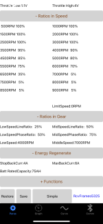
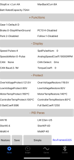
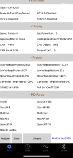
Is this a settings issue in the controller? Any help is appreciated! Added screen shots of the far driver app.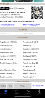


Last edited:
I just tried reducing the max line current setting to 200A thinking that if the controller and BMS settings were close, maybe the controller was asking the BMS for more and the BMS was going into "protect" briefly, but that didn't seem to make any difference.
There is a section in the Far-driver info about the "LM" setting in the PID parameters. Says it is the "Vehicle motor acceleration matching parameter" and 22 is the default and if jitter is felt (I guess that would be a description of what I feel) to try lowering the value until no jitter. It does make me nervous, though, as it states going too low can result in "MOE/OVER protection and even burning control". It suggest going down to 16 to start and then lower from there. I guess I'll try that next???
There is a section in the Far-driver info about the "LM" setting in the PID parameters. Says it is the "Vehicle motor acceleration matching parameter" and 22 is the default and if jitter is felt (I guess that would be a description of what I feel) to try lowering the value until no jitter. It does make me nervous, though, as it states going too low can result in "MOE/OVER protection and even burning control". It suggest going down to 16 to start and then lower from there. I guess I'll try that next???
The LM setting didn't seem to do much, or anything.
The only other piece of info here is that I had to swap a few of the hall sensor and phase wires to get the wheel spinning in the right direction. Maybe I need to do the auto tune again after that?
The only other piece of info here is that I had to swap a few of the hall sensor and phase wires to get the wheel spinning in the right direction. Maybe I need to do the auto tune again after that?
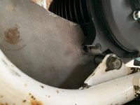
I figured out the clunking. It wasn't the motor after all. I'm a little embarrassed to admit that the chain had too much slack in it and I think in a high torque situation, it was enough to jump teeth on the sprocket. I also noticed that my motor mounting tab has broke off the motor. I don't know if this is a cause of the loose chain/clunking, or a symptom. Either way, it is very disappointing. After I noticed the slack chain, I tightened it up and had a few really good/hard test runs. Then the clunk came back. Could the motor torque have broken that tab? Not really sure how to proceed. I definitely need that mount. Maybe a good welder could cut off the rest of the tab and weld a new one on? Any other suggestions?

speedy1984
100 W
- Joined
- Sep 28, 2018
- Messages
- 248
The motor may have been under stress/wrong angle when the bolt went through,then adding torque has broke it.How have to mounted the motor to the frame?There is a motor direction tab at the top of the page lol,you are set in 1 change it to 0.Also make sure you are in D mode i.e the most power full mode and then re do auto learn.I run this motor on 28s voltage in my crf450 build on the same 96-850 controller and its fantastic
Similar threads
- Replies
- 52
- Views
- 1,710
- Replies
- 3
- Views
- 434
- Replies
- 6
- Views
- 711

