Zero-Draw, Solid State Contactor w/Precharge (Arduino)

oop! I should have recognized that schematic was from eagle, since that's one of the two I've used. Well, if you ever have problems with eagle not being 100% free (it has board size limitations, from what I recall) then consider switching to KiCad! KiCad has a slightly different workflow, but it seemed much more logical to me once I got through my first board. I agree, though, that it's a shame KiCad presumably wasn't as robust 5-6 years ago, when a lot of the open-source arduino people (Read: Sparkfun) settled on using Eagle.
 
Boards landed today from our friend at OSH park. Everything looks tits - I would be populating right now but I had a crazy day. Surfed earlier - the waves were killer - even too big for me. Hot too... like 85F. Went with a friend who is about to start working at Google - going to go over there and sample that fine cuisine soon. Interested to see that work environment. Then ate some awesome pizza at Pizza My Heart (the best IMHO) and on my way home I had the most crazy chance encounter... ran into dan hanebrink out front of my mail place. He had a bunch of his crazy bikes in the back of a truck... including the Hustler - which has one of my blue controllers with a CroMotor. We are going to ride tomorrow and do a little work over at my shop. Interested to see if his bikes can make it up my crazy shale hill to the ridge over my house.

I am rambling... not sure why

Steve and I have a new project going. An aspect of Gizmo - It is his idea (so I know it is a winner). It is going to be a CA add-on. Not the wireless temperature sensing (that is already in the bag afaiac). This one is better.... for the connoisseur. Luke will definitely approve as about every third phase out of his mouth is a complaint about this very subject. Going to keep it quiet until we have a prototype tho - too many chickens in the pot already.

Going out to dinner tonight with a couple of crazy guys - but before I do that I think I can sneak down to the shop to solder up the three different battery configurations. The wife blasted off in the car (with the kid) to go buy high chairs and crap like that in San Jose (craig's list hustle).

Yea man... I am living the dream over here. Caught a little too much sun - but that will just add to the character of my face. Women love craggy old guys with lots of stories to tell. I aim to fit the bill.

-methods
 
Methy,

Feel like sharing some artwork for component / trace and silkscreen for those of us with Etch tanks and time on our hands? I already presume the answer is No and I fully understand.

I'm going to be applying my very first contactor in a slightly different manor... I've had an EMC1200 break (I was a dunce and connected the leads backwards) which led to damage to the voltage sensing and relay (yea, that's their surge control and HV output disconnect method)... you would think it would have survived a reverse polarity connection but nope...

So I figure since everything else is still fine, I'll remove the relay and brake traces for all the input pack voltage sensing (which I checked, only manages the relay not the charger voltage that's a traditional TL494 IC chip) and whalla... guess I could do it now already based on the schematics you posted but you do such nice board design.

Oh, I'm really glad you decided to go with the 2S lipo it really is the way to go after weighing all the options (unless isolated DC->DC switching conversion can be done at pack level voltage of 100v) which just gets more complicated and also expensive.

Have you considered this approach in a new version of your LTC BMS (that would be version 5 right)? If stacked self powered 6803/4s were controlled by an isolated MCU using this approach it would make voltage potentials a non issue for the MCU / Brain portion.

Just an idea, worthless unless implemented.

A few more ideas:

1.) I can't recall if I saw an optocoupler place on board with this in your art / schematic. I would say it could be useful for many purposes your design will be adaptable to, perhaps include a place for it to interrupt the gate drive via an NPN triggered by the optocoupler - in non switch form, no NPN or opto need be placed but it would be a nice option.

2.) How difficult would reverse polarity detection be to implement, in it's crudest but effective form? As I've just learned properly done worth it's weight in gold?

3.) Have you considered making this an Arduino Shield? It's nearly pass through in stacking terms (one optically isolated pin triggers ON/OFF right) - this would make a fantastic shield much more reliable than Relay shields, more efficient and ... well not only would I purchase if it had been available (I've made my own based on one of your later schematics, for my own use prototyping) but I know 3 people who would also buy a minimum of 1 and 2 people who design mobile car stereos (think IASCA style competition systems) not to mention a few HAM and PACKET radio operators who would love to be able to replace their solid stage control boards. - Just a thought!

A few more questions:
What would reverse biasing do to this current incarnation of the circuit - in theory of proper operation it should block voltage and do nothing but what would be the outcome?

Patrick as always you have far outdone yourself, not in the aspects of the technical challenge of a Solid State Contactor (I'd loose the precharge control for charge delay) but more in your past, present and undoubted future contributions to the eBike cause but more importantly to the cause of sharing knowledge and empowering others, I for one Applaud you !

Warm Regards,
Mike
 
mwkeefer said:
Methy,

Feel like sharing some artwork for component / trace and silkscreen for those of us with Etch tanks and time on our hands? I already presume the answer is No and I fully understand.

I had 9 prototypes made and I am sure there are mistakes. I will just send you a unit to play with. Once I figure out what needs changing my next run will be 100pcs. You have always been an enthusiastic participant - I will gladly send you a few at my cost.

As far as my design - it is so dead simple that you could duplicate it in only a few minutes. I will share the eagle files tho if you want them (after I find any bugs etc)


I'm going to be applying my very first contactor in a slightly different manor... I've had an EMC1200 break (I was a dunce and connected the leads backwards) which led to damage to the voltage sensing and relay (yea, that's their surge control and HV output disconnect method)... you would think it would have survived a reverse polarity connection but nope...

So I figure since everything else is still fine, I'll remove the relay and brake traces for all the input pack voltage sensing (which I checked, only manages the relay not the charger voltage that's a traditional TL494 IC chip) and whalla... guess I could do it now already based on the schematics you posted but you do such nice board design.

Oh, I'm really glad you decided to go with the 2S lipo it really is the way to go after weighing all the options (unless isolated DC->DC switching conversion can be done at pack level voltage of 100v) which just gets more complicated and also expensive.

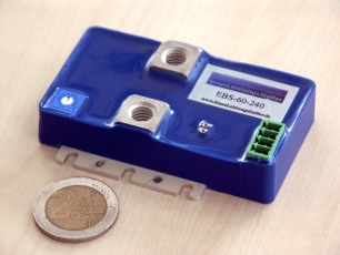
I populated a couple boards. One with nano-tek 2S, one with 40mAh coin 2S, and one with 240mAh coin 2S.

Have you considered this approach in a new version of your LTC BMS (that would be version 5 right)? If stacked self powered 6803/4s were controlled by an isolated MCU using this approach it would make voltage potentials a non issue for the MCU / Brain portion.

I dont even want to think about the LTC BMS. Folks have no idea how much effort went into V4 and it basically got tossed in the bin. I was so worn down after that all I could muster was the LVC boards.

Just an idea, worthless unless implemented.

A few more ideas:

1.) I can't recall if I saw an optocoupler place on board with this in your art / schematic. I would say it could be useful for many purposes your design will be adaptable to, perhaps include a place for it to interrupt the gate drive via an NPN triggered by the optocoupler - in non switch form, no NPN or opto need be placed but it would be a nice option.


You are getting into GizMo territory. Gizmo does all that shit - has Opto output throttle control, RTC, uSD, A-D's, D-A's, 8 temperature probes, current monitoring (dual hall), blah blah. This unit is the KEEP IT SIMPLE device. Everything else goes on Gizmo.

2.) How difficult would reverse polarity detection be to implement, in it's crudest but effective form? As I've just learned properly done worth it's weight in gold?

It is done with the thermal switch. If you apply voltage backwards it does nothing to the circuit (because the circuit runs on its own power) What it does do is short through the body diode of the mosfets (meaning it is on all the time) and if any appreciable amount of current flows the mosfets will get hot and flip the thermal breaker. So long as a user toggles the system after hooking up the high power I dont think there is really any problem with hooking it up backwards.

If I were to "do something" about it - it would be to put a second pair of fets on the board to make it truly bi-directional


3.) Have you considered making this an Arduino Shield? It's nearly pass through in stacking terms (one optically isolated pin triggers ON/OFF right) - this would make a fantastic shield much more reliable than Relay shields, more efficient and ... well not only would I purchase if it had been available (I've made my own based on one of your later schematics, for my own use prototyping) but I know 3 people who would also buy a minimum of 1 and 2 people who design mobile car stereos (think IASCA style competition systems) not to mention a few HAM and PACKET radio operators who would love to be able to replace their solid stage control boards. - Just a thought!

Gizmo is my arduino shield. For a dozen reasons this cant be a shield... power being at the top of the list.
A few more questions:
What would reverse biasing do to this current incarnation of the circuit - in theory of proper operation it should block voltage and do nothing but what would be the outcome?

Nothing - the current would just flow through the body diode of the fet and the switch would be rendered useless until polarity is reversed.

Patrick as always you have far outdone yourself, not in the aspects of the technical challenge of a Solid State Contactor (I'd loose the precharge control for charge delay) but more in your past, present and undoubted future contributions to the eBike cause but more importantly to the cause of sharing knowledge and empowering others, I for one Applaud you !

Warm Regards,
Mike

Ok, no more questions. :mrgreen:

-methods
 
Here is some pron

Here are the three battery profiles. The one in the middle has been eliminated... just too bulky. That leaves two options - the low capacity, disposable, low-profile coin cells... or... the low capacity but rechargable nano pack. I think I am going to offer both - as they have complementary features.

2013-05-02 18.15.33.jpg

Difference between the high and low profile coin cell holder (dual holder)

2013-05-02 18.16.02.jpg

I dont like how it turned out aesthetically - but this is a unit built up with hobby-king 10AWG and Anderson 45. I am going to offer the boards with no wires (cheapest), populated with small gauge wire, populated with large gauge wire, and populated with wire w/connectors (bullet, anderson, etc). I am going to charge an arm and a leg for the more built-up units.

2013-05-03 08.52.54.jpg

Now that I know the 3pin JST is actually smaller than the JST-XH I dropped, I may move one of the 2-pin connectors around so that they all exit the same side. I only moved one of the 2-pins out of necessity.

2013-05-03 08.53.22.jpg

In the upper left you have the 85V TVS diode that protects the fets (and allows us to go beyond 100V for charging). Then you see the two surface mount (D2pak) 4330 fets - 4.5V fully on gate, 100V, ~4mohms rdson. In the upper right is the 8 pin uController (ATtiny) that will run Arduino. The bottom middle is the regulator (much larger than it needs to be, but SOT-23 parts really suck for hand placing / quality control / reliability). The row of caps are 1uF for the batteries, 22uF for the output of the regulator, and 0.1uF for the bypass of the chip (yea I know I could have gotten it a little closer).

In hind sight I am pretty sure that I want to add a 5V TVS Diode to the rail to sink off any nasty spikes that come from the fets. This will probably be mandatory for reliability - but I like to start simple and add parts as needed. The engineering approach of sprinkling every possible protection part on the board you can think of - then saying "see? It works" has always annoyed me. I say build it as simple as you can and only add the protections that are needed and produce results!

2013-05-03 08.53.55.jpg

Since I am posting pictures - here is some real shit work. I accidentally cut a phase wire on a CroMotor while we were working out the procedure for adding the thermisters. Since these are such high dollar motors (with so much juice handling) I wanted to be 100% sure that every single strand of wire was getting utilized. So... the most direct way to do that was to solder a lead to each! After getting known-good electrical contact with every strand I then wound the bundle (for mechanical straign relief... which is a must... because if enough current flows the solder will re-flow and you have to keep it all together). Yea - so I wound the bundle for mechanical support and then re-flowed all the solder into a huge monolithic block :mrgreen:

I am confident that this electromechanical connection is as good or better than shipped from the factory.

How the hell do they strip the wires so well there? F'ing nightmare getting that coating off.... They probably use the nasty chemicals.

2013-05-002.jpg
2013-05-003.jpg

-methods
 
So methods, where is my Paypal request for my boards... Ill take 2 and I can populate the fets and the smt if needed,
Minor bending of pins I don't mind, plan a small just cable for 2s lipo source anyway.

-Mike

PS: you seemed to indicate your efforts with the LTC 6308 were less than desirable if not downright bs, should I presume you'd recommending passing them up for the atmel or ti series stackable but 2-6s asics? Totally unrelated but if the LTC is that prone to issues, I'm not using it!
 
http://www.sinusleistungssteller.de/ sell since some weeks a solid state contactor with 'fuse', 'soft start' etc. capabilities (all text in german only), r

EBS_Basic_k.jpg
 
nieles said:
300 euro for the cheapest one

Ouch. Nice package though. Methods solution is definitely way better for the ebiker.
 
Those things look cool but I agree - 60V is a non-starter. It is pretty easy to do this stuff at low voltage - but once you get up to 100V or 200V+ it is a totally different story. That is why I dropped all the advanced features. Precharge can be done by an IceCube cable. Fusing can be done thermally. Over-current can be done thermally as well (though not as good or as fast).

Good enough tho

I intend to sell mine for more like 30 EURO... so even though mine have much less functionality they are an order of magnitude cheaper and *almost* an order of magnitude higher voltage.

Speaking of which... I think I am finally ready to cycle back to this project. Just got home from Vacation and my pockets are empty :D So that usually means it is time to pick a project off of my shelf of things that are 90% done and finish it. :wink:

At least all the hard work is already done. Nothing is harder than trying to develop a money making product from scratch with no money lol.

Wait till you guys see my vacation picks :twisted:

-methods
 
I know you do.
Now imagine if it was your only source of income.

I am thinking about taking on some contract work to increase cash flow. I am just too irresponsible to be my own sole source of income... truth is I just don't care about money enough to spend my time worrying about it and trying to make it - but then I have to spend my time worrying about the side effects of having no money.

Easier for me to take on 20 hours a week of someone else's worries. Officially on the prowl for a contract that actually interests me.

-methods
 
methods said:
That is why I dropped all the advanced features. Precharge can be done by an IceCube cable. Fusing can be done thermally. Over-current can be done thermally as well (though not as good or as fast).

-methods


Think your unit will survive being switched on when connected to a 24 fet controller @ 100V? You know it's going to happen sooner or later. I weld the contacts on my big ass DC relay every month or so. At least with the relay I can file the contacts smooth and get it to work again.
 
nicobie said:
Think your unit will survive being switched on when connected to a 24 fet controller @ 100V? You know it's going to happen sooner or later. I weld the contacts on my big ass DC relay every month or so. At least with the relay I can file the contacts smooth and get it to work again.

Well - first off it is not intended to be used for that - that would be the main discharge path. This version is intended to be put inline with the charge path or put inline with the controller power switch (i.e. the controller regulator power line) so there are no extreme load situations.

That is how I will *suggest* people use it. Some will of course use it in the main discharge path, and to answer your question - YES... I am fairly confident my fets can survive that. The question is if your controller cap bank can survive.

Welding the contacts on a relay is to be expected if you dont have a precharge resistor - you really need to have one. Slapping to pieces of metal together is really different than charging the gate on a mosfet. I am just going to slam it on... so sure if you looked real close at the inrush current with a $200 scope probe you would see that I am abusing the fets... but experience shows that you can get away with this for a very long time - especially when it is only being switched on and off from time to time.

Your "big ass relay" really is no comparison to what I am doing here. It probably takes what... 3W to keep that thing open? On a 600WH pack that is 200 hours worth of run time - so that means that if you forget and leave your contactor closed it will only take 8 days to drain and ruin your battery - not including the overhead of regulating down to 12V (if that is what you are doing). My switch uses orders of magnitude less current and requires NO bias. No 12V regulator or source - it runs for free - so you could leave it on for a thousand years and never drain the pack dead.

My switch also turns off if it gets an external signal - like for LVC or HVC - hard to do that with a big ass relay.

-methods

-methods
 
methods said:
nicobie said:
Think your unit will survive being switched on when connected to a 24 fet controller @ 100V? You know it's going to happen sooner or later. I weld the contacts on my big ass DC relay every month or so. At least with the relay I can file the contacts smooth and get it to work again.

Well - first off it is not intended to be used for that - that would be the main discharge path. This version is intended to be put inline with the charge path or put inline with the controller power switch (i.e. the controller regulator power line) so there are no extreme load situations.

That is how I will *suggest* people use it. Some will of course use it in the main discharge path, and to answer your question - YES... I am fairly confident my fets can survive that. The question is if your controller cap bank can survive.

Welding the contacts on a relay is to be expected if you dont have a precharge resistor - you really need to have one. Slapping to pieces of metal together is really different than charging the gate on a mosfet. I am just going to slam it on... so sure if you looked real close at the inrush current with a $200 scope probe you would see that I am abusing the fets... but experience shows that you can get away with this for a very long time - especially when it is only being switched on and off from time to time.

Your "big ass relay" really is no comparison to what I am doing here. It probably takes what... 3W to keep that thing open? On a 600WH pack that is 200 hours worth of run time - so that means that if you forget and leave your contactor closed it will only take 8 days to drain and ruin your battery - not including the overhead of regulating down to 12V (if that is what you are doing). My switch uses orders of magnitude less current and requires NO bias. No 12V regulator or source - it runs for free - so you could leave it on for a thousand years and never drain the pack dead.

My switch also turns off if it gets an external signal - like for LVC or HVC - hard to do that with a big ass relay.

-methods

-methods

Just make it and take my money already
 
Thanks for taking the time to reply. You're the best.

I do have a pre-charge circuit but it seems that every time I let somebody try the bike out they can't resist flipping the main switch. Every once in a while I forget too. I am getting better though, as I hate to have to take the side cover off in order to fix the damn relay.

I did buy one of the nice small relays that Big M was selling but have a feeling that it will act the same as what I now have. I'll be trying it the next time my big ass relay screws up. If it doesn't cut it, I'll be buying one of yours. If it blows... Oh well, I don't mind the loss when testing. It won't be the first time. :mrgreen:
 
On almost all large scale EV's they just permanently strap a precharge resistor across the relay. I am beginning to think of our bikes as high power enough to warrant that... tho... if a controller is left on enough current can creep through to drain our tiny packs so much faster.

Suppose we calculate it out at a month
30 days
15 AH pack
Call it 75V

So we have to draw say... less than 10AH in 30 days with 75V

10AH / 30 days = 333mAh / day which is about 14mAh constant

75V / 14mA = about 5K

So - if you string a 5K resistor across your contactor terminals you will be good for a full month of leaving it on (minus contactor power). Most EV's do something more like 750 ohms etc.

Chiggy CHeck it - you should do that.

-methods
 
Hmmm... call it a 10K resistor
That will pretty much squelch any issues of draining and if left on long enough will assure precharge. Probably will need to have your switch turn off the controller regulator along with opening the contactor to make that work.

Speaking of which - if you just turn off your controller when you open your contactor then there will be no draw on the caps and they will stay at the same state of charge... so no SNAP when you turn it back on.

-methods
 
Why must everything be so hard?

Use a big one of these, with precharge enabled by lifting the protective lid.

toggle%20with%20cover.jpg


Problem solved.

:)
 
Ok RF - lets see it. :)

Make your proof of concept, then knock together a prototype, then lets try to produce 10 of them.

Brainstorming an idea that *could* always looks easy... actually producing something that *does* work is hard. First issue I see that you will run into is exposed 100V DC contacts - not sure how you will get around that. Also - your precharge resistor will have to be small enough to precharge almost instantly - which is not really realistic. Many Precharge schemes take many seconds or even minutes. The first 70% of your Precharge will be fast - but once the DV drops it will slow down following the charge profile of the caps.

Build it - and if it works... I will make it available to the masses.

I believe there has to be a lock-out if the solution is to be mechanical. Something where the main power wont engage until the precharge has crossed a certain percentage.

That said - I never precharge. I just slam the connectors together. :wink:

-methods
 
rf said:
toggle%20with%20cover.jpg


Problem solved.

:)

I agree with -methods. I wouldn't want exposed 100vdc contacts anywhere on my bike.

The coil on my big ass contactor is rated 100v. If there was a circuit that would energize the pre-charge resistor but delay turning on the relay, that might work?

I sure would like to get rid of that monster relay.
 
Wow. It was sort of a joke. But I guess it's not anymore. You guys have hammers in your hands and are only looking for nails. (Or fancy electronic solutions.)

Radio control models are pushing lots of power these days too. One of the equipment manufacturers warned against using pre-charge resistors with their controllers, saying they would cause damage. They said, if you must, something like 1.8 ohms was as high as you should go.

Leaving their bad controller design aside, that was an interesting idea. Even a small resistor value (and one or two seconds of delay) will provide a fair amount of protection. Take most of the sting away.

So two power switches. Each providing power through a small pre-charge resistor. Turn them on, one after the other, and get full power.

Or make it part of the battery connectors. Two connectors. Plug them in one at a time. Either one provides pre-charge. Together they provide full power. The time between plugging in two connectors should be plenty to pre-charge the caps.

Hmm. Way cheaper and better.

Can someone please draw a schematic? Thank you.

Richard
 
rf said:
One of the equipment manufacturers warned against using pre-charge resistors with their controllers, saying they would cause damage. They said, if you must, something like 1.8 ohms was as high as you should go.
I wonder exactly what the issue is there?

The constant rate ramp precharge thing I did seems to solve a lot of issues and is super easy to implement.
 
Back
Top