Zero XU & DS

j bjork

1 MW
Joined
Aug 31, 2018
Messages
2,001
Location
Linköping, Sweden
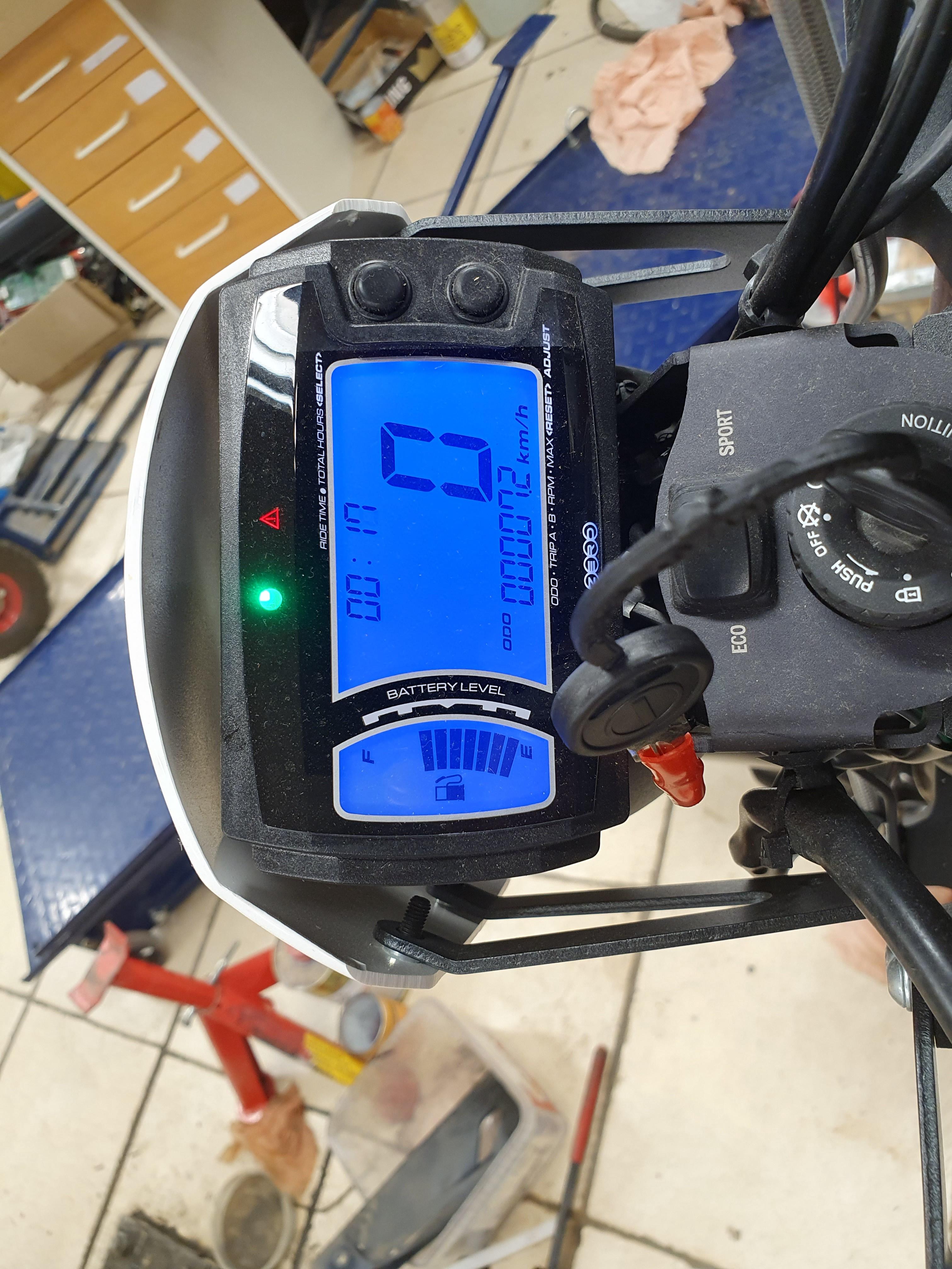
A friend left these bikes at my place:

KKKbMv3.jpg


SX1wMNG.jpg


Both are new, but probably a little test driven. Now with dead batteries.

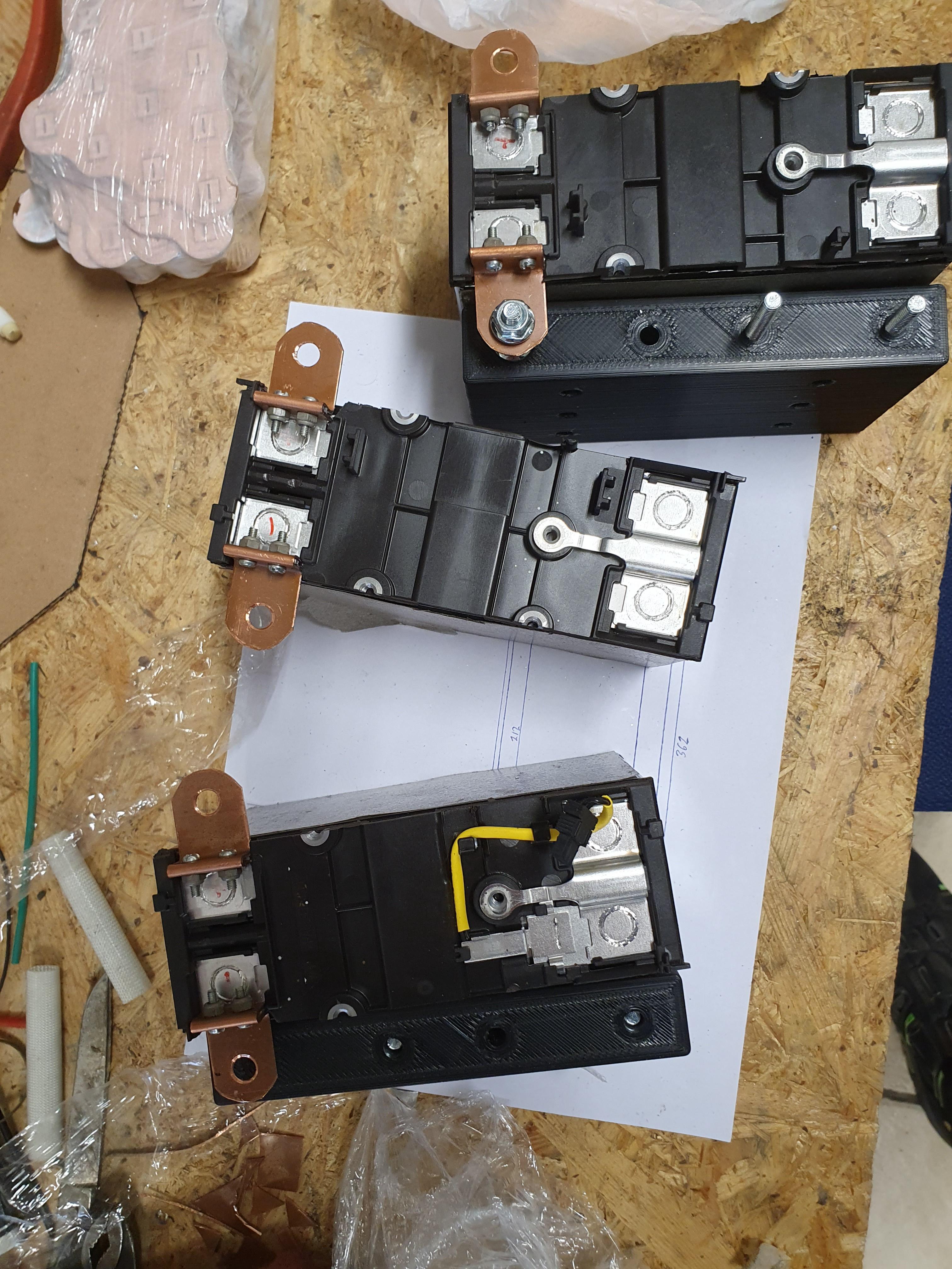
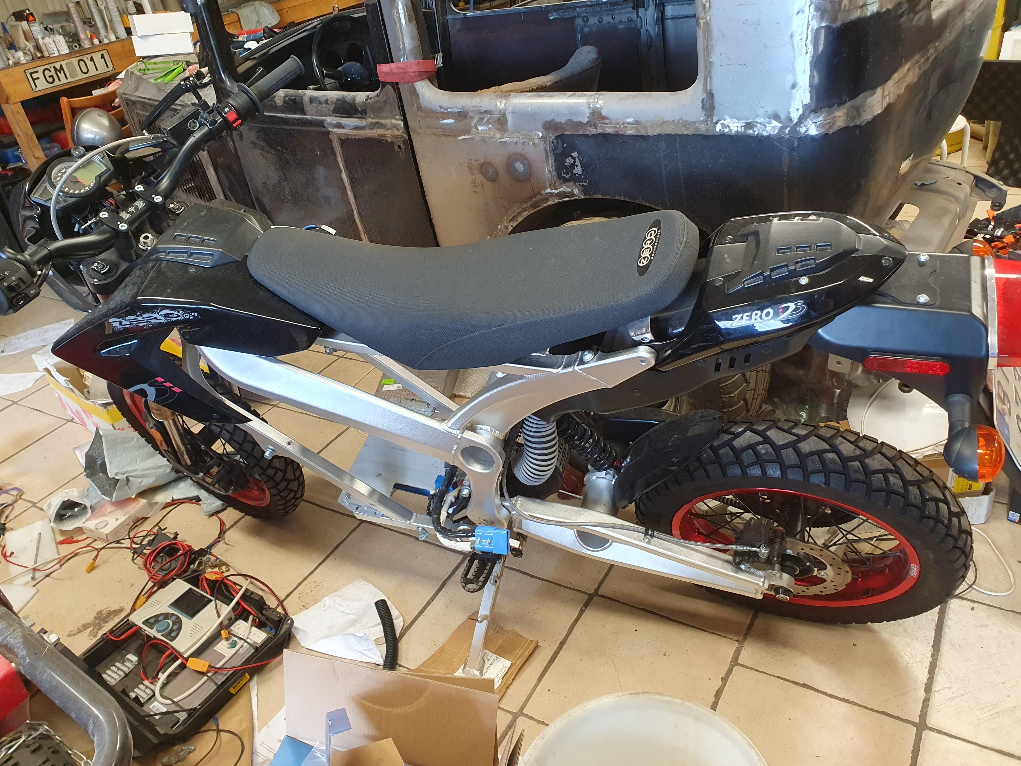
I have opened them up, the ds with dc motor has a big 14s battery:

VrmAUAq.jpg


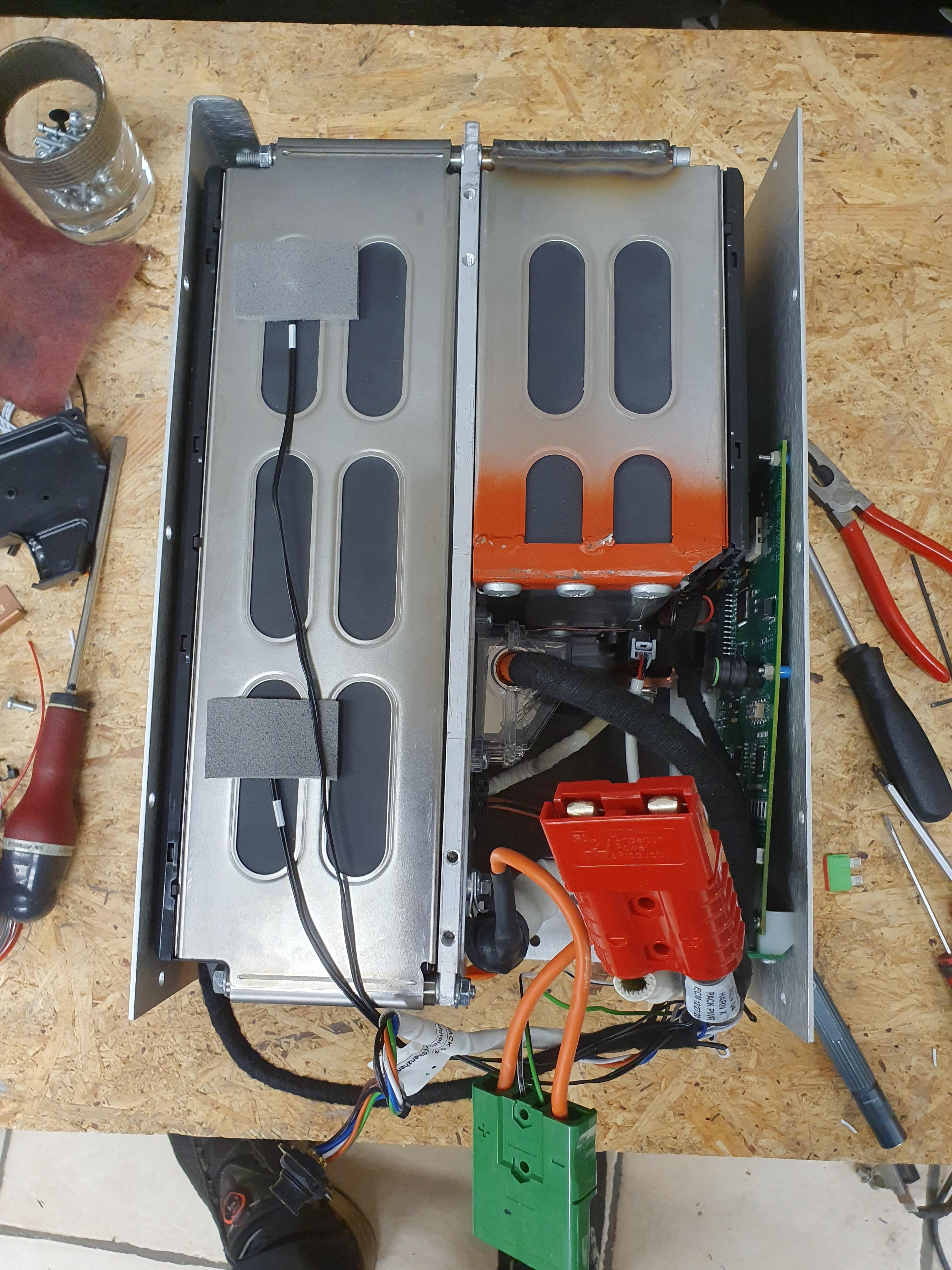
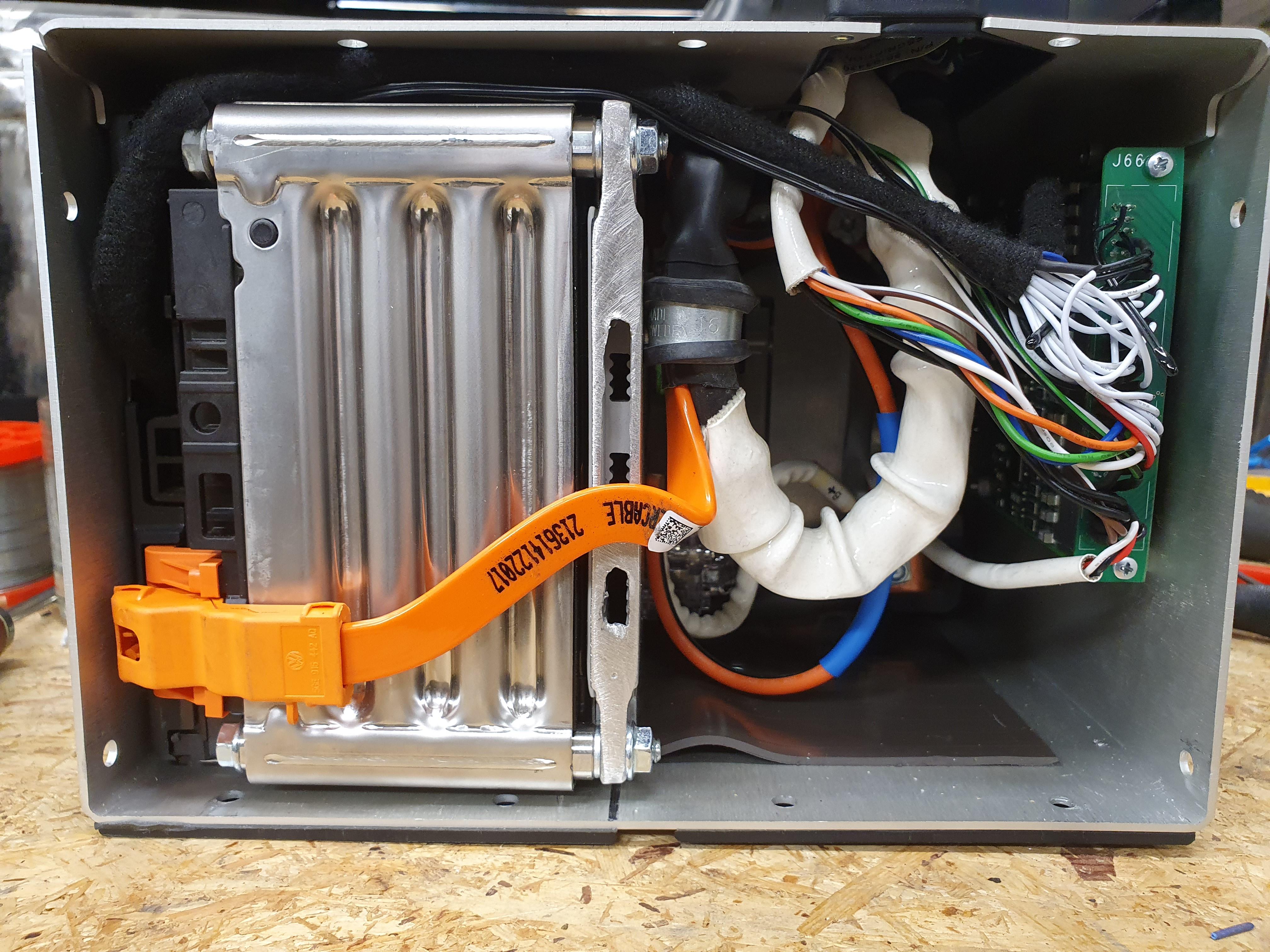
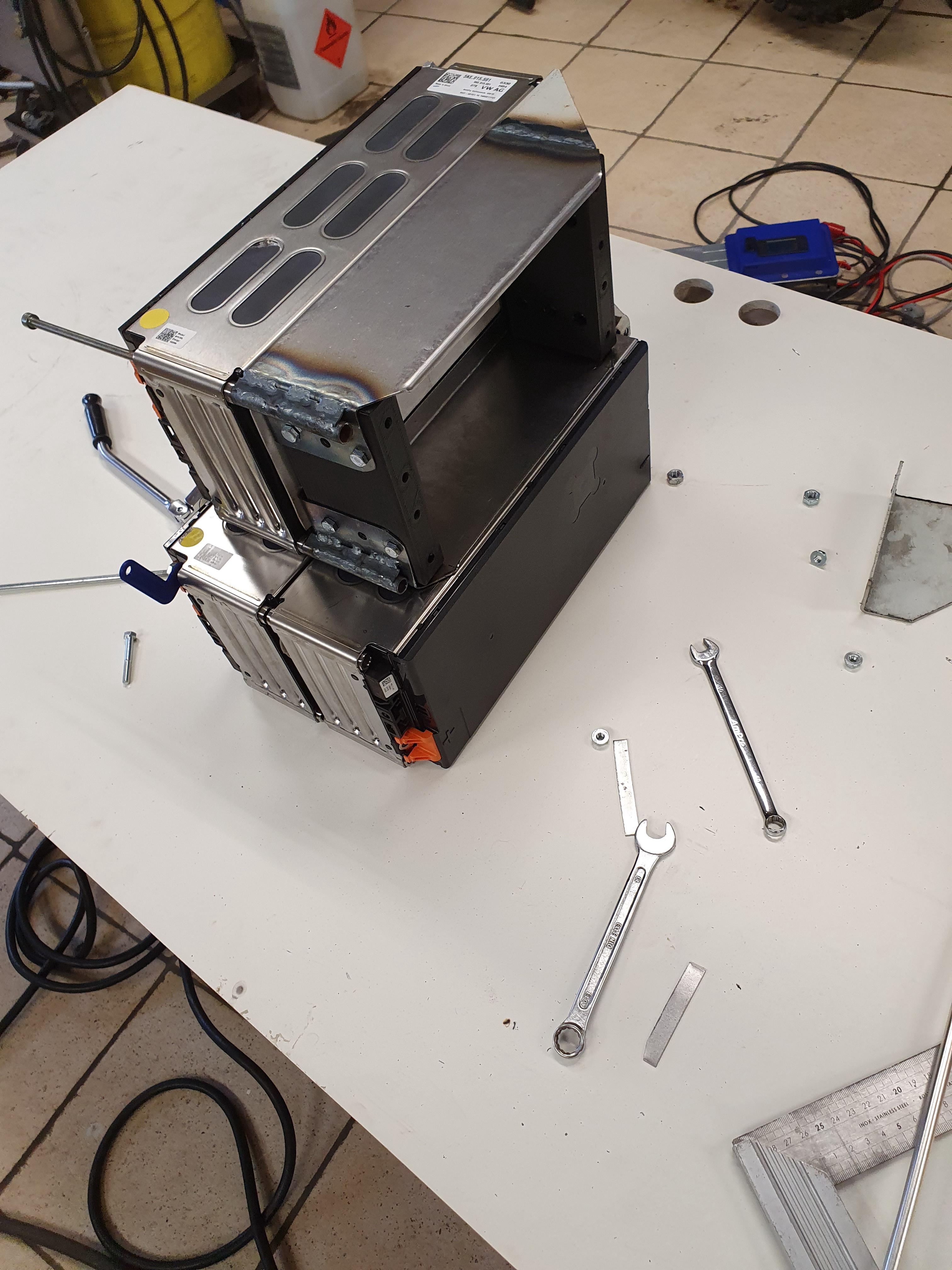
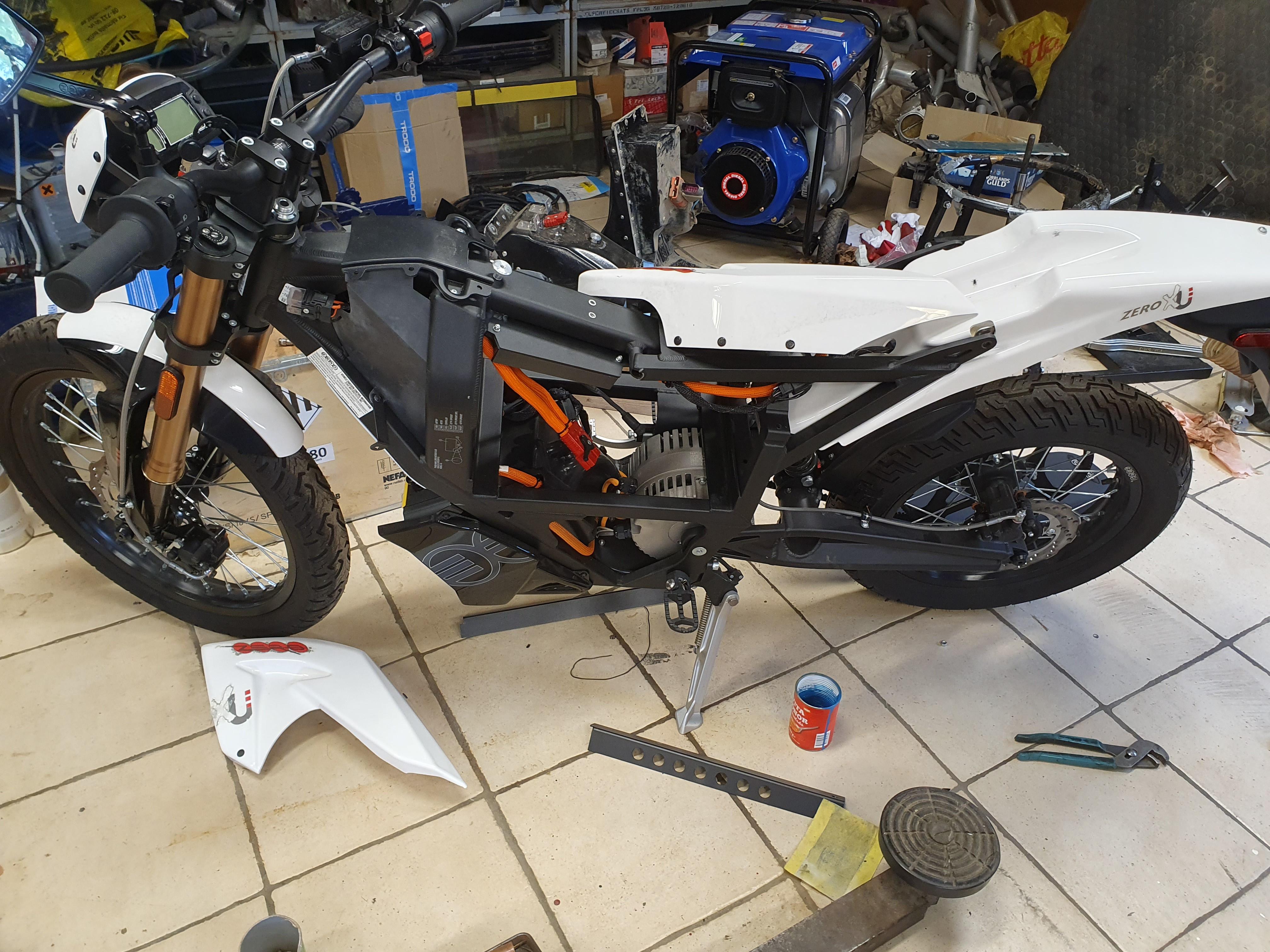
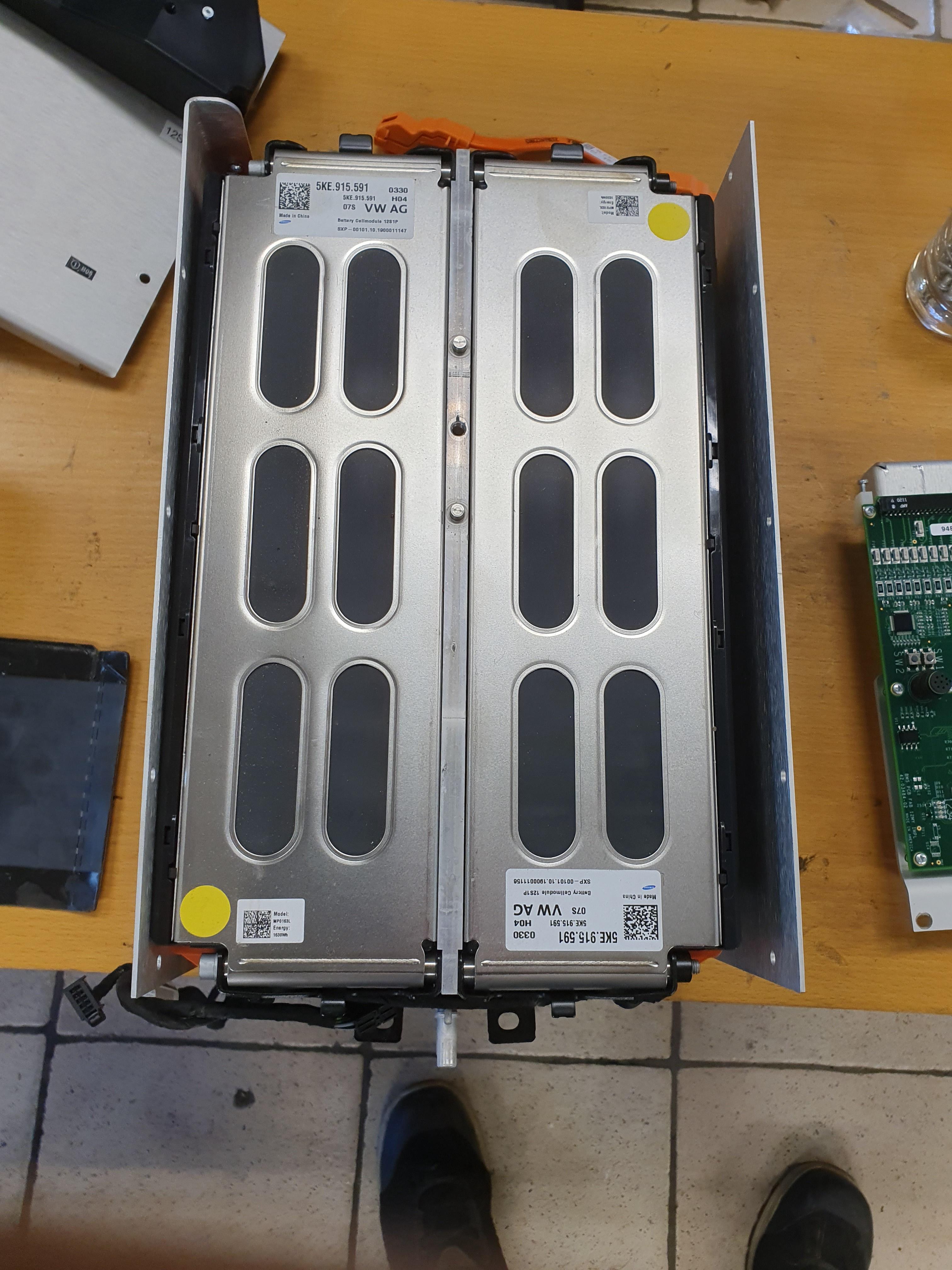
The XU has a 18s battery:

VLzr92z.jpg


At the moment I am trying to decide what to do..
The XU seems to have a sevcon controller, I think they are 48 or 80v.
My guess is 80v then, so it should be no problem running 24s if I could reprogram it.

UWTMBCj.jpg


Like this, but it would be pretty crowded in the box.

But if I build a 18s, I should be able to run the standard bms and everything should work right?

oAGJSwZ.jpg


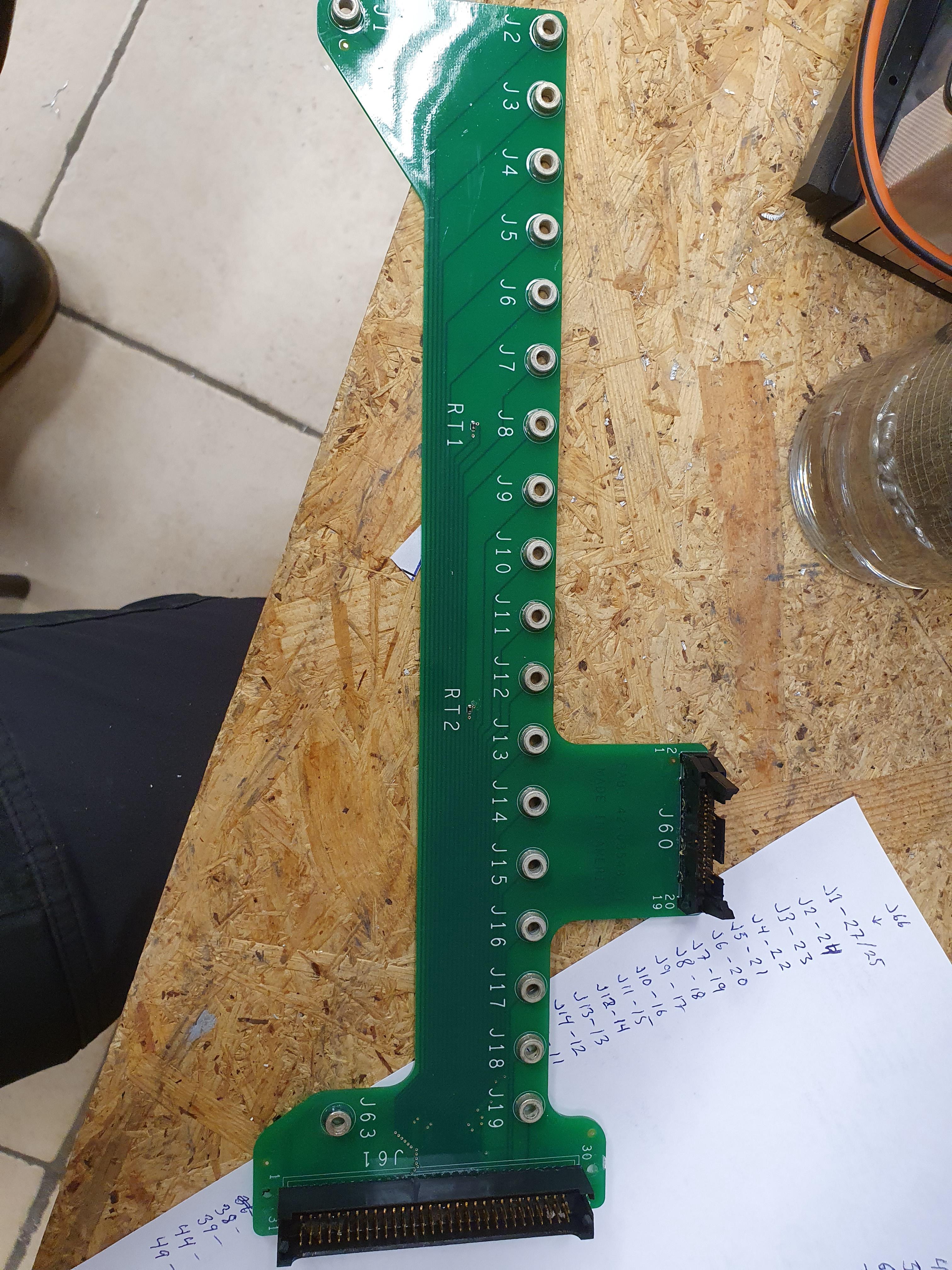
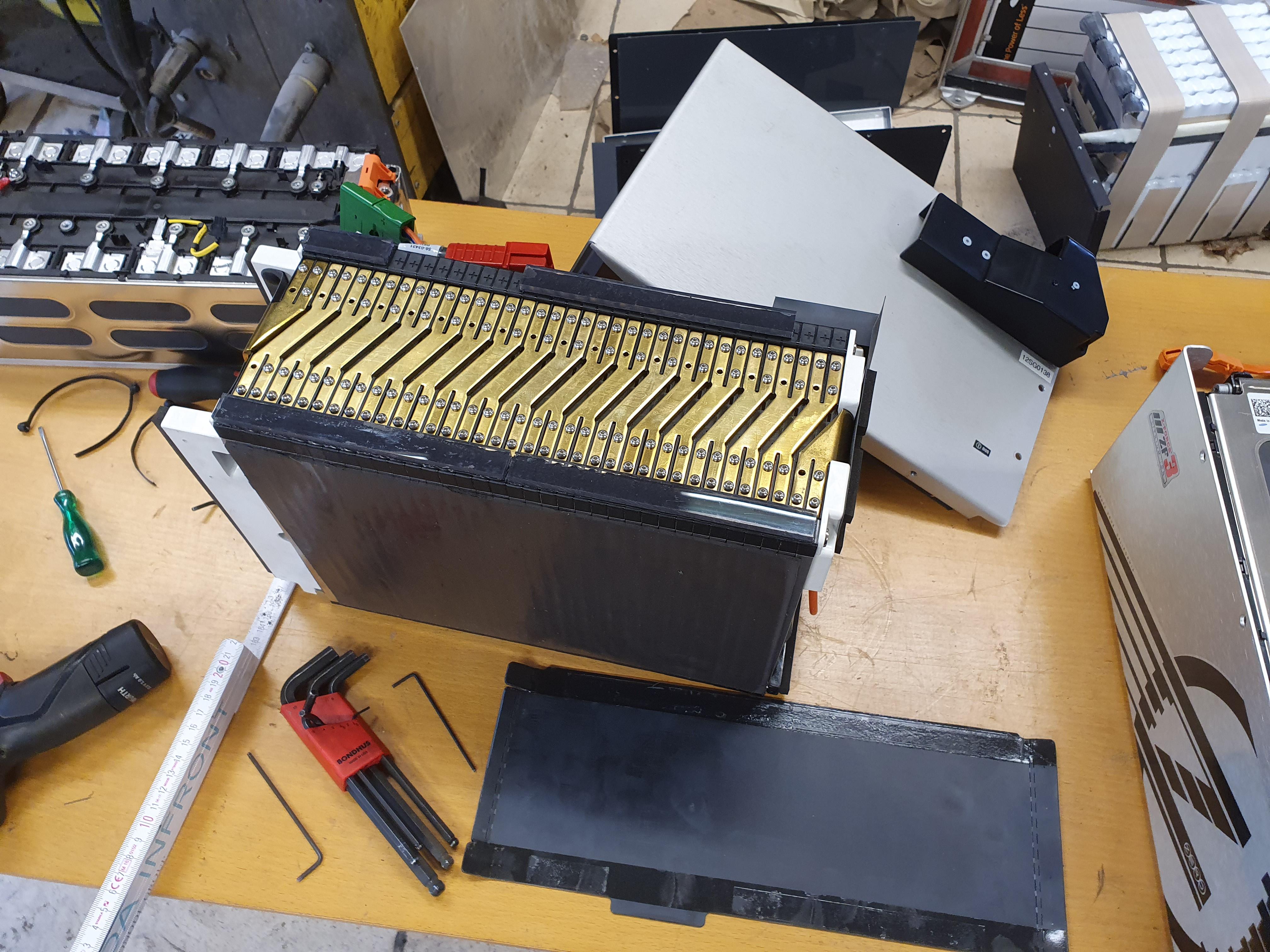
There is a connector that you would normally reach trough a hole in the case, is that needed?
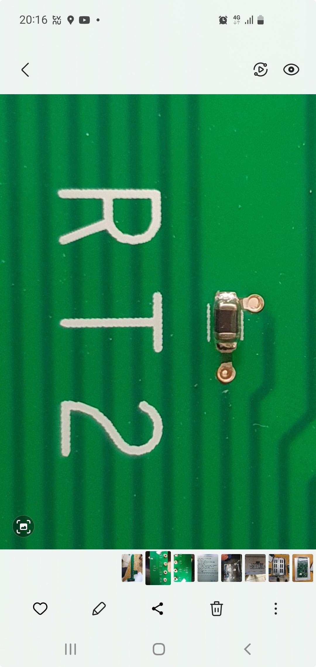
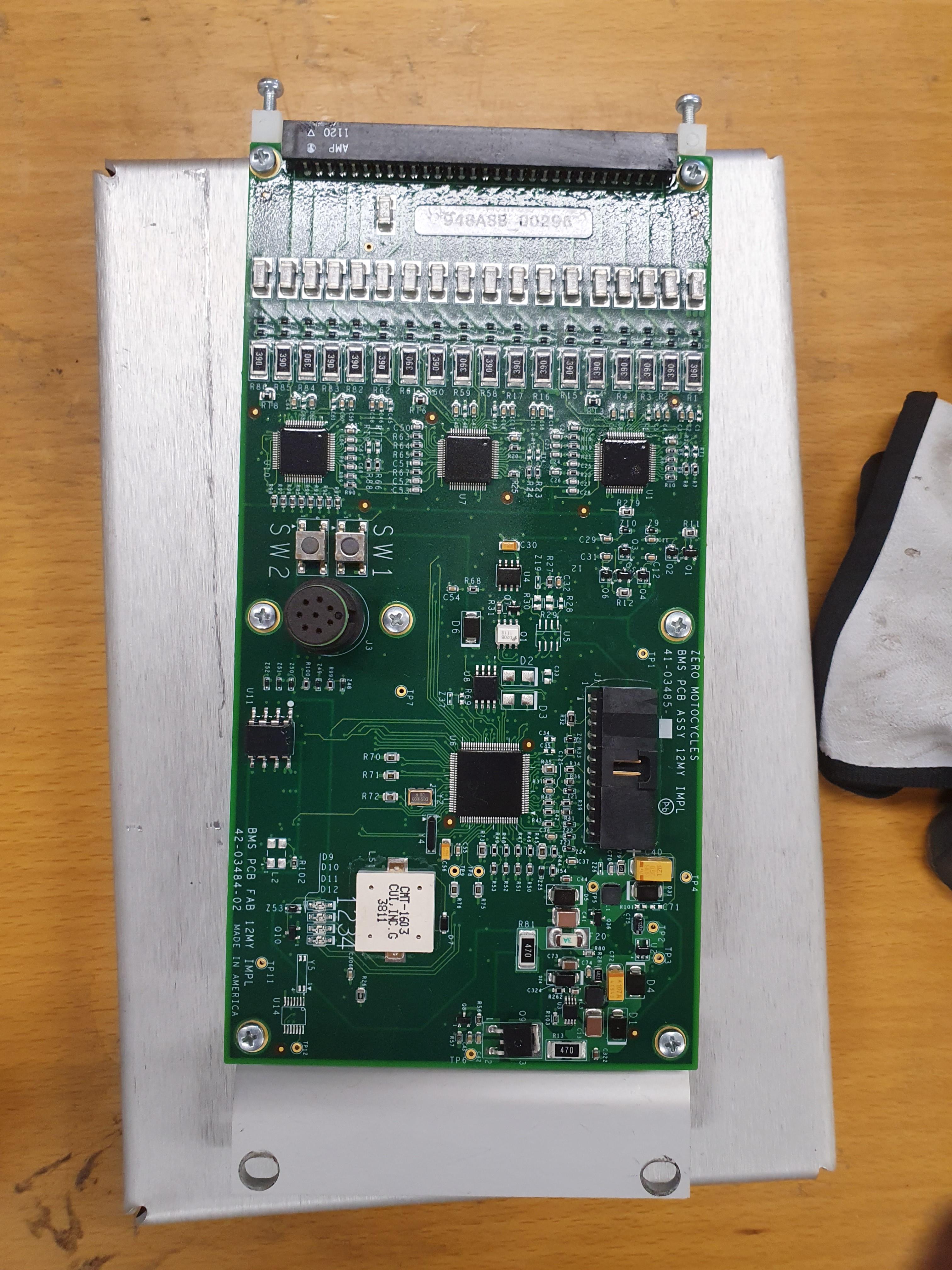
There are also some leds that you can see trough a glass in the case, what are those for?
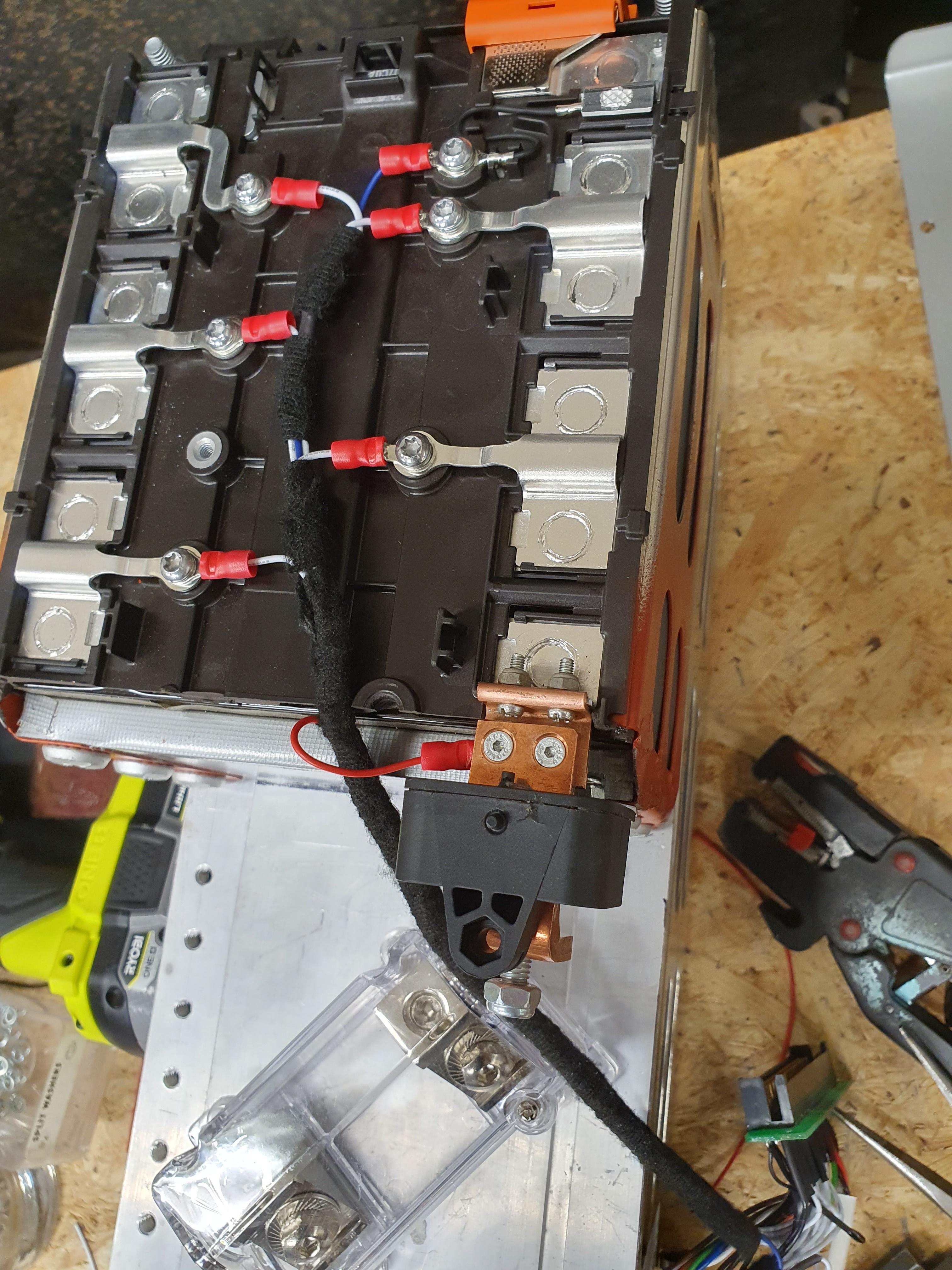
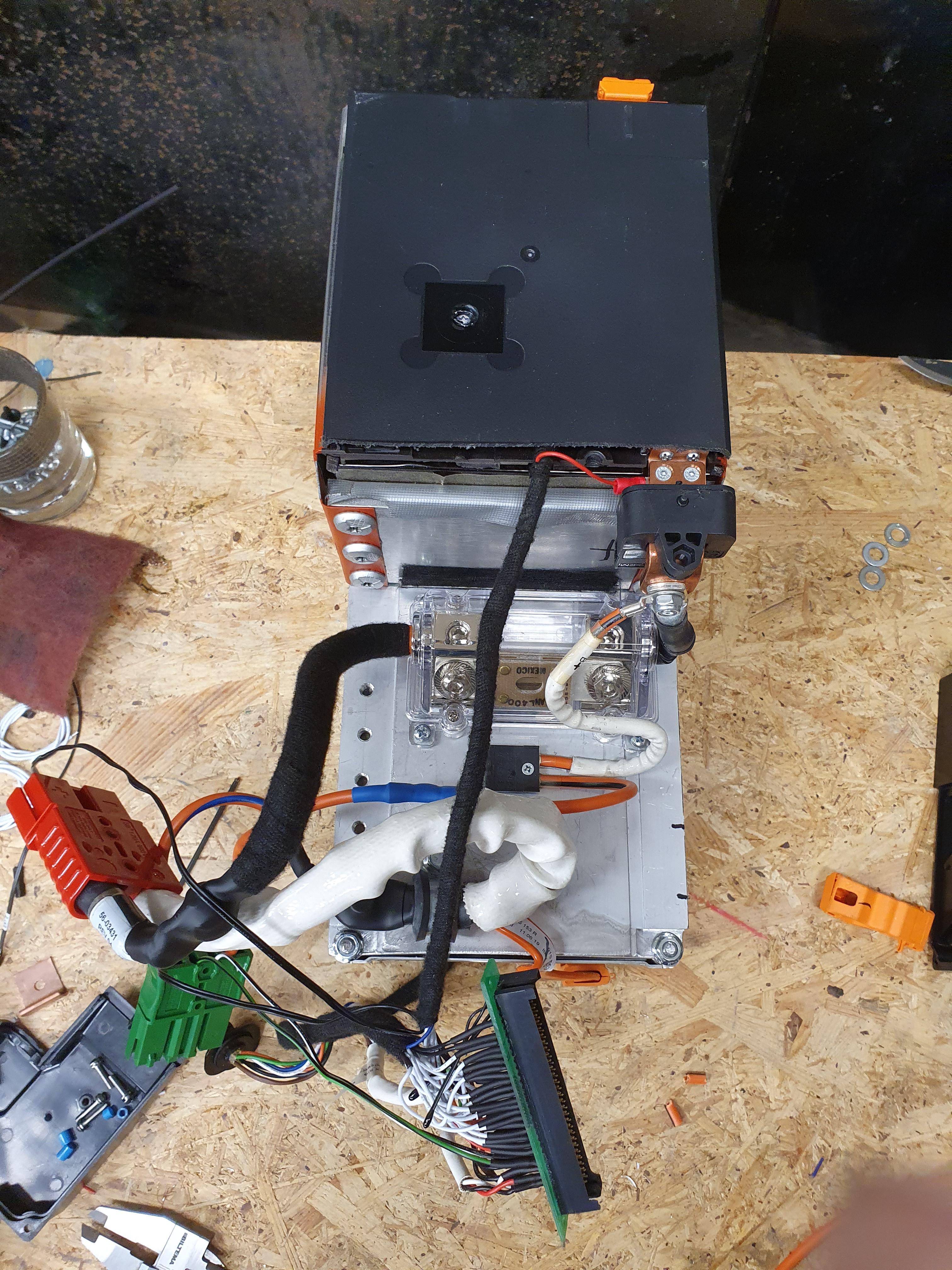
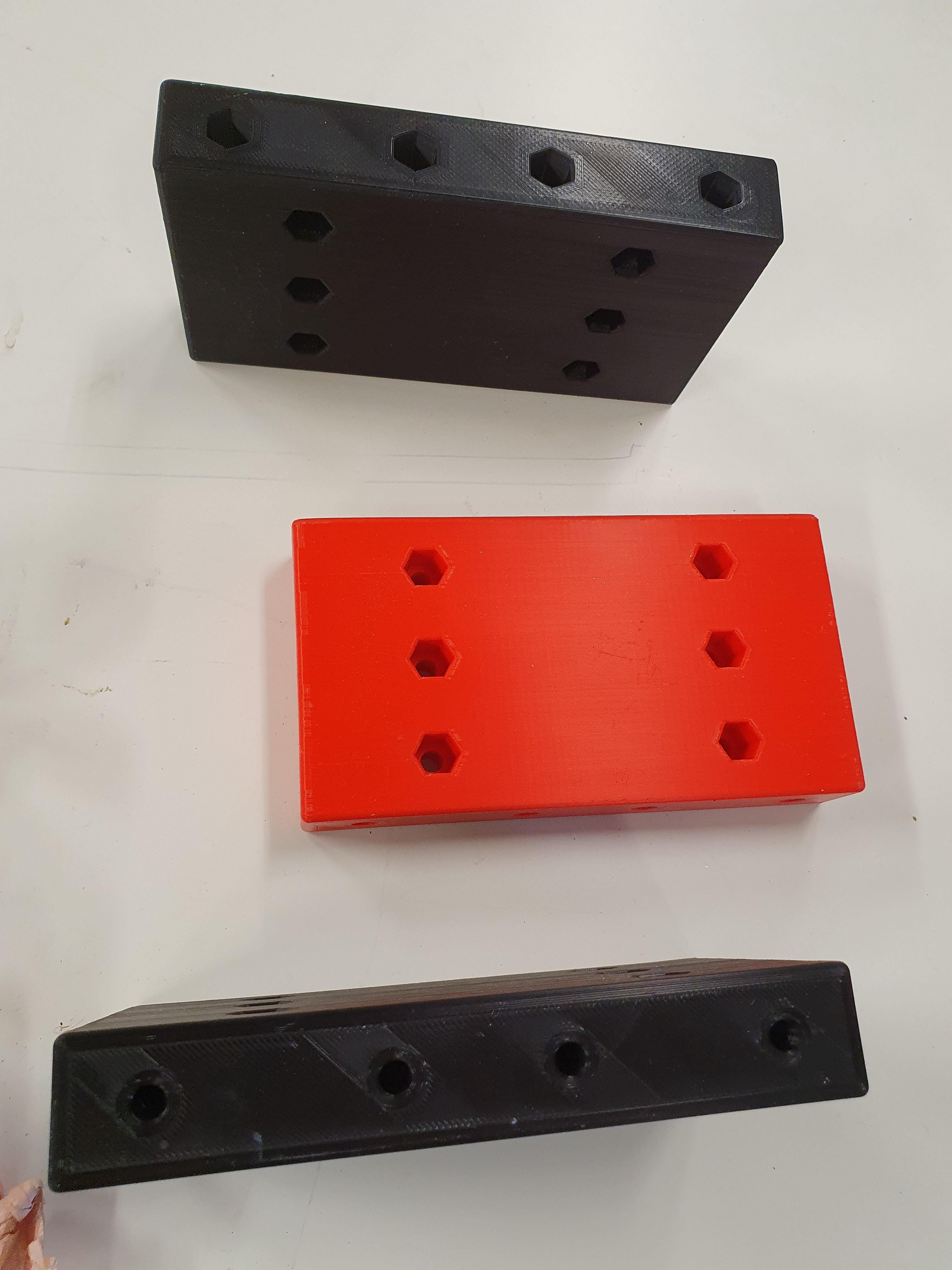
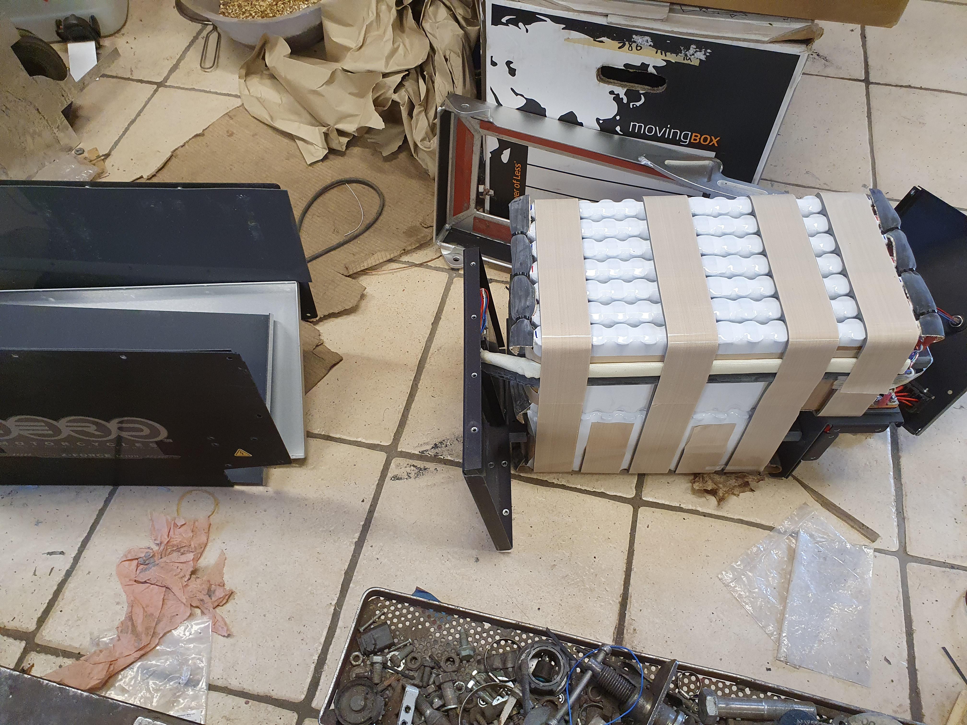
The interior of the battery would be a bit different on mine so the bms wouldnt fit were it normally were mounted;)
 
I decided to build a 18s battery for the xu, and try to get it to work with the bms.
I cant use the connection pcb, so I am reverse engineering that to find what pins everything goes to.

Q6OOXeE.jpg


xHhaIrg.jpg


I am not sure if I have found pins for RT1 and RT2 though. I thought they were some kind of resistor (Resistor Temperature?)
I expected to get a ohm reading when I found the right pins, but it dosent seem to happen.
There are other temp sensors, so I dont know what what use they would be.
Any ideas?
 
In the picture, one of the connections on RT2 looks like it didn't solder properly. It may be just an optical illusion. You could measure it right on the board to test.
 
I havent been updating very much here, but here are a few pictures from the process:

xwVUrgj.jpg


I placed the current sensor on the positive pole on the battery.

a41qdIm.jpg


2sKXHrA.jpg


Q26GZFx.jpg


As I used one 12s module and a half module I got a decent amount of space in front of the half.
But very tight in the front and back of the whole module.

The batteries were pretty well built except for one thing.
They are not even close to watertight.
I have heard the saying "it never rains in southern California", but come on:

8vwoBYb.jpg


W6a3qot.jpg


And the sides is on top of the top plate, so water flowing on the top will get in..
In a way it is a god thing that there are gaps in the bottom, so the water can get out again :rolleyes:
What if the owner thinks it is a good idea to wash the bike with a hose or pressure washer?
 
Dosent seem to be much interest in these bikes?
Well, I havent had it on top of my priorities either. But I made a go for it, and tried to get the ds done too now.

It would be easy to make a 24s2p battery, then I could just stack the modules 2 in the bottom and 2 on top of them and bolt them all together.
But then I probably have to change most of the electrical system, so I decided to go for 14s3p anyway.
I will use 3 of the 12s1p modules and parallel them, and build a 2s3p module.

heBAb6I.jpg


I cut up a module and made 3 of these 2s blocks.

I 3d printed these separation blocks:

9lwX8ax.jpg


But these are pla, that seems not to be very suitable so I later made new ones in abs.
It will look something like this:
l2cdGPe.jpg


I had to move the top 2 modules forward, to have room for the bms (that seems to be cast on the back plate of the battery housing)
and make room for the wiring.
 
Back
Top