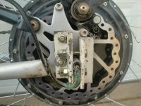
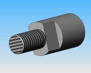
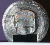
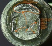
5304 axle snapped after 5700 miles

Yep welding an option too, but then you get the usual heat stresses if you are not careful. So then you are into heat treating/de stressing etc..all psosible of course

here is what I was thinking

just a quick rough paper sketch, totally not to scale

cable goes in from LHS thought 8mm cross bore drilling, 9 or 10 mm still gives good amount of meat on shaft if LHS axle nut is 30mm :shock: ..but witha huge torque plate like this, as long as it is secured to frame well enough, then axle nuts almost become an irrelevance. So dispense with the nut and use the start of the cross drilling, tapped to take a set screw and big flat washer or plat, and the end of the axle is then flush o the side of the frame...clamping dropouts required of course, clamping up from underneath
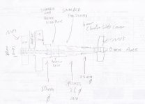

IMG_0001.jpg
 
Deleted and moved to hear to start a different discussion since that seems to be branching off somewhere new

http://endless-sphere.com/forums/posting.php?mode=quote&f=3&p=596704
 
NeilP, if you're looking for the root causes of the axle snap, don't forget the most obvious one. You were pushing it way past the point it was designed for.
 
I swear it never even got hot officer, it was only doing 15mph and it is only pushing 250W..looks it says so just there on that sticker :D

Umm do not think I am pushing it that hard..not as hard as some, and I am certainly always gentle on the throttle, no off-roading, or curbs and I slow down for pot holes.

I do run it at 100volt, but not that often, once or twice a week maybe.
My standard settings at 84 volt are about 90amp battery, 190 or 200 phase, lower when I run 100 volt
 
You can pinch a hollow axle to the failure point. That has been a concern of mine with the dirt bike. Like nobody has seen me post this pic, but just in case, this is my pinch dropout on the dirt bike.mongoose pinch dropout.JPG

I make sure not to overtighten it, and make it into an oval with cracks developing in the axle.

Too much power would surely twist off the axle, but I run only 72v 40 amps max. On the CA, I rarely see more than 2000-2500w anyway.

I keep wishing somebody at 9 continent would build a motor with an axle more like the Heinzmann. That torque arm really works. Under that cover in the pic above is a bearing and axle about 2" diameter. Tons of room for wires to exit safely, and lots of area for the torque arm to bear on. Best of all, It can fit any bike, any dropout, any design unmodified. No oversize nuts and washers, no stress on dropouts whatsoever with a round 9.5mm axle.
 
NeilP said:
Umm do not think I am pushing it that hard..not as hard as some, and I am certainly always gentle on the throttle, no off-roading, or curbs and I slow down for pot holes.

I do run it at 100volt, but not that often, once or twice a week maybe.
My standard settings at 84 volt are about 90amp battery, 190 or 200 phase, lower when I run 100 volt
So you don't push it as hard as some, but you're pushing it. Here's some info that I'm sure you have seen before:

http://www.electric-bikes.com/betterbikes/phoenix.html

There are three motors in the Phoenix Crystalyte 530X Series. They are all brushless motors and are the same physical size. They can be used with either 36 volt (3640) or 48 volt 40 amp (4840) controllers...

Phoenix Cruiser (Crystalyte Model 5304) Use the Cruiser when you have long steep hills or do not want the speed of the Racer. Cruiser reaches 30 MPH in 13 seconds, and will sustain its top speed under more varying conditions. The Cruiser with the 4840 controller will gain a little speed on our test hill, the steepest one east of the KU campus. This is an extreme hill that even the Racer will not climb without some pedaling.
If the above vendor knows his stuff, then his implicit upper recommended limits are 1920W (48*40) and 30mph top speed. Those limits, to me, are already high considering that the 9C 2807 is only rated for 500W.
 
In my opinion the stub shafts (that are threaded) are just too small and the shaft material not optimum in all these designs that are capable of say 1500 watts and above. I think it was farfle that I recommended he machine his shaft out of "stressproof" steel. It is a 100ksi rated allow that machines like butter.

Neil if you have crack propagation lines on the fracture surfaces, then it could be fatigue. They will look like the ridges that waves leave in hard sand at the beach. They are called Lueder lines. http://adsabs.harvard.edu/abs/1998SPIE.3396..282I I could not make out if this feature is present in your photographs. This fatigue failure will be highly correlated with the allow and heat treatment (if any) of the original axle material.

I have thought for a while that the flats for the dropouts should be in the full diameter axle, sketch below:
bikeaxle.jpg
 
Neil
If the splines are causing grief with regard to making a new axle. Have you thought about locating the the stator onto the shaft by using grub screws? you could tap the stator and tighten the screws using an allen key. The grubscrews could locate into small indentations in the motor shaft.

BTW i have repaired a broken shaft on a BPM (not a crystalyte). It snapped right where a circlip locates. I opened up the shaft where the wires came through, i TIG'd all up again and drilled the axle shaft from the other end for the wires. 3 phase wires and 5 hall wires. The stator had a keyway luckily. Anyhow, it's fixed and i've been riding with it this week.
 
dogman said:
You can pinch a hollow axle to the failure point.


Oh yes I know, i saw that occurring on the little under powered Thompson Euro Tourer motor on these '10 minute wonder ' clamping torque plates...almost crushed it completely...I was talking to someone while tightening the other side. Cant find pics...that frame was just as a test bed for the Timing adjuster tool, so aesthetics was not a consideration..only thought was stop it spinning

file.php
 
bigmoose said:
In my opinion the stub shafts (that are threaded) are just too small and the shaft material not optimum in all these designs that are capable of say 1500 watts and above. I think it was farfle that I recommended he machine his shaft out of "stressproof" steel. It is a 100ksi rated allow that machines like butter.

Absolutely..Stress proof steel...what is that when you try and order it from a supplier...I was thinking EN24..or maybe something with a higher than normal vanadium content, to give slightly more 'give' or 'flex' to the steel


bigmoose said:
Neil if you have crack propagation lines on the fracture surfaces, then it could be fatigue. They will look like the ridges that waves leave in hard sand at the beach. They are called Lueder lines. http://adsabs.harvard.edu/abs/1998SPIE.3396..282I I could not make out if this feature is present in your photographs. This fatigue failure will be highly correlated with the allow and heat treatment (if any) of the original axle material.
I do not know fithe lines you seek are on here, but i would say it had to be stress fracture from fatigue . The flats on the end of the axle were held very securely in the torque plates and the centre of the axle was getting all the flex at the solder where the threaded portion started, rocking back and forwards under every acceleration and braking action . A torque clamping system with some give..see this thread would I believe help relieve that
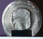
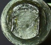
Here are some better pics
P1130051.jpg
P1130052.jpg


bigmoose said:
I have thought for a while that the flats for the dropouts should be in the full diameter axle, sketch below:
Yep, but my plan is to go with max axle thickness right through to the end without machine the side covers..so near on 30mm on the disk side and 20..or 25 on the gear cluster side...whatever the maximum will poke through the side cover.
have flats machined on for the clamp system, and have the axle ends flus with the torque clamps. If anything to secure at the ends it will be a central drilling, tapped to accept a set screw and large washer or plate bolted in the centre and maybe at each corner too in to the side of the torque clamp.

Unfortunately never even used e CAD app, so can't even begin to raw it up for you
 
I am not a metallurgist, but with the little tutoring I have had over the years, this is what I see in the pictures.

The first one appears to have a crack initiation site at the root of the milling for the flats on the left. Looks like it propagated radially.

P1130051A.jpg

The second one looks like there is a big carbide grain at like 4 oclock and that the Lueder lines emanated from the grain outwards and met the other crack.

P1130052A.jpg

The final failure appears at the top as a ductile tearing.

Wish my good friend and metallurgist was still alive, he would give an expert opinion in a minute that we could take to the bank.
 
If the dropouts are not parallel, the axle is forced to curve and vibration occurs with rotation. That is the major cause of axle or bearing failure. Those Chinese motors are not made with quality material and seriously lack manufacturing precision. It is not surprising that we have occasional failures at the power level that we run them. I just had a bearing failure on a new motor that has less than 200 Km, and everything was perfect in the installation. Just a crap bearing, i guess i got the lucky number.
 
MadRhino said:
If the dropouts are not parallel, the axle is forced to curve and vibration occurs with rotation. That is the major cause of axle or bearing failure. Those Chinese motors are not made with quality material and seriously lack manufacturing precision. It is not surprising that we have occasional failures at the power level that we run them. I just had a bearing failure on a new motor that has less than 200 Km, and everything was perfect in the installation. Just a crap bearing, i guess i got the lucky number.

Did your bearing actually rotate freely from new?

I took my motor apart when I first got it, and the inner race was seized in the bearing when the bearing was in the cover. Remove the bearing from the side cover and it worked perfectly, although a little rough.
problem was the side covers were machine a fraction under size,and they compressed the bearing too much when bearing was pressed into the cover, had to machine a fraction of the side covers to allow bearings to work. More of a polishing than actual machining. Think I span the cover up in the lather and used fine emery paper
 
Bigmoose,

Good motors have the axles almost exactly like your drawing, though the flats do extend onto the threaded portion to accommodate a larger diameter nut. I take it that while the discontinuous threading is less than optimum, they determined that the greater surface contact area and at a greater radius with the face of the nut offset the thread issue. I haven't had thread problems. On every motor I've purchased that is rated over 1000W, the dropout fits the axle like you've drawn, and have larger diameter axles with flats made for 12mm or greater dropouts. One of the factories even cuts the flats on a slightly different plane, which I surmise is to create a tighter fit in the dropouts. They also come with dual torque arms, though they're the hole thru type that aren't sufficient for regen, because they never have a precision machined fit. The torque arms are a solid 1 piece unit made of a stronger alloy that bolts to the frame, so in addition to the added spinout protection, they ensure the motor doesn't come off the bike/scooter if it does.

As I understand China has pretty strong consumer protection laws (eg Those putting poison in the baby formula to raise the vitamin ratings probably got a death sentence), and they've put over 50 million electric 2 wheelers on the road in the last 5 years, the overwhelming majority of which are hubmotor driven. That means they must be making some good quality motors, and just because plenty of cheap junk gets dumped on the export market doesn't mean we have to buy them. Unfortunately, inferior quality motors have become the most popular around here, which is baffling due to the premium price.

John


bigmoose said:
In my opinion the stub shafts (that are threaded) are just too small and the shaft material not optimum in all these designs that are capable of say 1500 watts and above. I think it was farfle that I recommended he machine his shaft out of "stressproof" steel. It is a 100ksi rated allow that machines like butter.

Neil if you have crack propagation lines on the fracture surfaces, then it could be fatigue. They will look like the ridges that waves leave in hard sand at the beach. They are called Lueder lines. http://adsabs.harvard.edu/abs/1998SPIE.3396..282I I could not make out if this feature is present in your photographs. This fatigue failure will be highly correlated with the allow and heat treatment (if any) of the original axle material.

I have thought for a while that the flats for the dropouts should be in the full diameter axle, sketch below:
 
amberwolf said:
If you're gonna use a larger bearing anyway, whynot just enlarge it so much that you can pass the phase wires between the axle and the ID of the bearing? Problematic on the chain side, but if you don't *require* the rear disc brake it would be easy on that side (assuming the cover thickness allows for it).

If you do need the disc, you could make an adapter plate to go from the motor cover to a modified rotor.

Alternately just make a whole new side cover with mount points for a modified rotor and the new bearing size support.
Hi amberwollf
Can you explain this in more detail may be with a diagram or something
I just do not get what you mean
You say pass the phase wires between ID of bearing and the axle, but that is just physically not possible without creating a gap or slot in the axle or something.


Thanks
 
Make a bushing that fits the ID of the larger bearing and OD of the axle. Put holes or a channel for wires in the bushing. I'm using the word bushing loosely for lack of a better on, but I made one to fit a little geared hubbie axle and a 2" ID bearing. I put big holes for the wires and a number of big holes for air intake since it was a ventilated rig.
 
Well my new axle arrived from Kenny at Xlyte today, and I had an idea

Rather than machining a new one or repairing the old, I wondered about turning two bits of bar to the same diameter as the section just before the 14mm thread and flats. Drill them and internally tap them then spin them down over the new axle to totally hide the threaded portion
Then V out the joint between axle and new portion, weld it up then turn back down to correct diameter, so something like 20mm
Then I can put flats on the 20mm new section to secure in the clamping torque system
 
John in CR said:
Make a bushing that fits the ID of the larger bearing and OD of the axle. Put holes or a channel for wires in the bushing. I'm using the word bushing loosely for lack of a better on, but I made one to fit a little geared hubbie axle and a 2" ID bearing. I put big holes for the wires and a number of big holes for air intake since it was a ventilated rig.

I started work last week on the lathe to make this axle, then have been waiting 10 days now for a new knurling tool to arrive. Those 'splines ' we see are not splines, they are a rolled on knurl, so had to order a new lathe tool for that.

But with regard to this collar arrangement, has any one actually seen or tried it? In theory it sounds OK, but in practice the dimension do not add up, unless one goes for a thin axle again.

Imagine a 20mm axle, in a 30mm bearing..so 10mm for he collar. That is only 5mm each side, and it needs to extend from the bearing inner all the way through the casing to the outside, so longer than the standard plastic liner tube we see by about12mm.

So you need a tube of dimensions 30mm external, 20mm internal, 5mm wall thickness, and 40mm long. This then needs to be drilled with 4mm holes to full length to pass the wires, leaving half mm wall thickness in 5 places. That is not going to work. The alternative is splitting it, but then you do not have any protection for the wires from the rotating hub casing.

We also toyed with the idea of offsetting the axle in the bearing.

Only other alternative I can see to use this idea is to go with a smaller axle again, which puts us back to square one
and then try and drill holes cut a slot in it to make a
 
For the one I did it to I used a 2" ID bearing, so I had room for any size axle.

It may be a bit late but have you seen Farfle's hollow axle for his double Pi? Something like that doesn't work to fit 10mm dropouts, but that's too small for higher power motors anyway. All scooter hubbies have more thickness at the flats.
 
One of the more recent Magic Pie versions uses wires thru a collar like this, AFAICR. I have seen a pic of another company's motor that does this, too, but can't recall what it was. It's here on ES somewhere.

There's no reason that the bearing inner race has to rub on the wires--if you secure the race to the collar, even with something like loctite, it should stay in place and not spin and thus not rub on the collar or wires.

Or make a U channel for each wire on the ID of the collar, against the axle, where it will not rub as it shoudln't spin with the bearing on the outside of the collar. Given your dimensions stated, the U channel would allow a full mm of outer collar thickness, rather than 1/2mm on either side, if that is important. If you want extra security, notch the collar and axle with a keyway and use a key, but I don't think that shoudl be necessary.
 
amberwolf said:
There's no reason that the bearing inner race has to rub on the wires--if you secure the race to the collar, even with something like loctite, it should stay in place and not spin and thus not rub on the collar or wires.

Was not the bearing inner race I was thinking of, that is stationary anyway, but the inner rotating surface of the side cover, if one was to make a full depth slot.

amberwolf said:
Or make a U channel for each wire on the ID of the collar, against the axle, where it will not rub as it shoudln't spin with the bearing on the outside of the collar. Given your dimensions stated, the U channel would allow a full mm of outer collar thickness, rather than 1/2mm on either side, if that is important. If you want extra security, notch the collar and axle with a keyway and use a key, but I don't think that shoudl be necessary.

Yes, i did consider this, but was thinking that once you put in a big slot for the 3 phase wires, plus another slightly thicker one in for the halls, there is not a lot of body left on the tube. Will try one later and see what it comes out like.

I am thinking now, maybe make this collar, with a slot, and also a slight slot or flat too on the 20mm axle, o give a little more space, then sweat and press the collar over the axle, possible even silver solder it into place.
 
Since the cover is all *outside* the *outer* race of the bearing, (at least on the 9C covers; maybe it's different on yours?) there should be no way for it to ever contact the wires running thru even a completely open slot cut in the tube. Only the bearing's inner race could contact them, AFAICS.
 
Of course it does..the wire has to pass out the centre of the side cover along with the axle, and that hole in the side cover is 30mm (just under) on a 5304.

This collar cant just be the width of the bearing, it has to extend all the way to the outside world to protect the wires from where they pass near the side cover, replacing what used to be done by the plastic sleeve
 
Back
Top