5304 axle snapped after 5700 miles

Ok. I guess I am not visualizing it correctly, because in the versions I've seen pics of so far, it isn't an issue. I'll have to ponder some more.


This is my 5-minute MSPaint version just showing the bearing and collar and axle, from POV of axle end. Doesnt' show the cover or whatnot.

Bearing outside, both Outer and Inner races are light gray, bearing section/seal is dark gray, collar is red, axle is black with dark gray flatted sections. White "holes" in collar are for halls (oblong) and phases. Probalby the hall hole can be just a regular small hole, as even if you put temperature sensor wires and even a whole second set of hall wires thru as a spare, it doesn't need to be very big.
 

Attachments

  • bearing collar axle.PNG
    bearing collar axle.PNG
    1.7 KB · Views: 2,422
Yep your picture is exactly what I am seeing and visualising too.

but now rotate that 90 degrees and look at it side on as if looking at the bike from the back ( or front)

You now have the axle in the horizontal axis with the wires running across the top of it...they gotta come out the hub.

I'll try a quick paint sketch too
 
Hub side cover in green
part of stator in purple/pink

wire(s) in light blue

Hole in centre of beaaring and the side cover are both 30mm..actually hole in side cover is fractionally less than 30mm..say 29.5, so I either machine it out or make slight step in the collar...making it less than 5mm wall thickness
 

Attachments

  • Untitled 2.png
    Untitled 2.png
    7.6 KB · Views: 2,419
Possibly still need to make that collar with a shoulder to butt up against the inside of the frame and dropout, to prevent compressing the side of the frame against the side covers
 
I posted two pictures..I just added that lip to act as a shoulder to locate the frame against.

If you do not have the red collar extending all the way out, then you will need something like the original plastic collar, otherwise we are back to the wires running close to the inside bore of the side cover
 
I am talking about the green cover's "lip" that sticks out past the brake mount.

I do realize you'll need the collar to extend to the frame, unless you make a lip on the axle itself to do that (which will weaken the axle).
 
Ah , the green 'lip'..probably a bit thicker in the picture than in real life...it is only the thickness of the brake disk, in fact probably a bit less
 
Well we have just had the best 5 days of our summer, the first two I was on standby, and did not get called out, and the last three were days off..so what did I do ? Did I enjoy the glourious weather on the beach ..no I have spent the entire 5 days in the workshop making the new axle...Bugger

but at least the axle is done..after a selection of failures
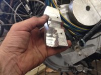

IMG_0444.jpg

From the top
No. 1 Broken axle
No. 2 test blank I made up 2 years ago, can't remember why now.
No. 3 New axle sent by Kenny @ Xlyte...looks the same but slightly different dimensions.
No. 4 Axle made to dimension of the new axle from Kenny......
No. 5 Made to correct dimensions....after a 12 hour day...I'll just do one more pass....the tool tip snaps and cuts a groove down to 15mm...just visible in the picture
No. 6 Finally a complete axle and spacer for wires on Day 4

Today I did work on a smaller lathe and combined milling machine., cut the flats and tidied up the slots in the collar and stuck the collar to the main shaft with DP420.

Tomorrow I'll press the axle in to the stator..and probably glue that with DP420 too.


The splines are rolled on
I counted 66 splines, and a un-splined diameter on the original axle of 25.35mm.
This works out to a spline pitch of 1.2mm. SO the splines are rolled on using a parallel knurling tool of 1.2mm pitch. This will give the 66 splines
IMG_0437.jpg

I did not have a proper broaching /slot making machine so i used the lathe. After making the collar, I held it in the lather chuck, and locked the chuck with a ratchet strap.
I then used a boring bar with modified tip, in the tool holder, and ran the tool holdr back and forward to cut the slot for the wires in the collar.

IMG_0449.jpg


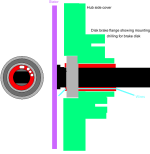
If you are wondering why there are so many holes for the disk brake...I had to re drill and tap them...Xlyte had them all off-centre
IMG_0451.jpg

Finally today, machine the flats off on a mill and cut slots in the collar and tried it for size

IMG_0454.jpg


I used a 47x30x9 bearing on the wire side, instead of the standard 47x25x12, so that allowed a 30mm shaft ...or in this case a 30mm collar . The main axle going out either side is now 20mm, with flats made to 18mm , sothinest part of axle is 18mm across the flats.

Slightly differently to standard, I will be fitting it to the bike with the flats horizontal rather than vertical. One of the flats is full length and makes the wire slot slightlh bigger. This will be at the bottom of the axle .

Going to cut the back section of the dropouts out, and make two or 4 bolt clamping brackets to hold the axle.Will need custom brake and derailleur mounts too...but not even looked at that yet..just going to get the wheel fitted to the frame first
 
Hold off on the judgement till it actually works...was not sure what steel to use. Think it was EN8 I used in the end.. the original steel was not that hard
.
I had hoped to use case hardening compound on it, but my mates oven has packed up ..and localised heating with gas will likely result in warping...so I am going to leave it un hardened..and hope
 
How much different is the 9C/cromotor spline.. I might ask you to make me an axle, my friend :twisted:

you would think one would replace a failed hub motor after 5000 miles.. but some people are determined. I'm sure the end product is a motor that will last another 40,000 miles. :)
 
No idea on the 9c or Cromotor splines, not seen one, but on the Xlyte, there are no matching splines inside the stator !

Yes, that surprised me too, the stator just has a plain drilled hole with a possible slight taper, but even that I am not sure of. It is just a press fit into a smooth bore
I was not going to put a key way, but am reconsidering now. Easier to do it before I assemble than to have to do it if it spins, as has happened to some in the past.
I may just leave the splines and glue with DP 420


If I was to take my time in to account, then making the new axle was not cost effective
Although it did take 4 solid 10 hour days with the lathe to produce the finished product, a lot of that was taken with me making mistakes and trying out ways to do the job, had not used a lathe for 20 years, and then it was only as a student

As for making new one for you, probably cheaper for you to get one done locally.
If you were to want to replace an Xlyte axle like mine, I can pass on the dimensions and a local machine shop could knock one out quicker than I could.

Looks like a 1.2 mm pitch parallel knurling tool is what is needed to roll the splines on.

Better still, anyone here reading this good with CAD apps of any sort? Maybe someone could create a CAD image from my dimensions, then if someone wants one and has access to a machine shop with CNC kit they could get it made even easier.

A couple of concerns I do have is in regard to steel type to use and wether to case harden or not after. Ideally yes, but then you risk warping the shaft.
The other is differences between axles from Xlyte production runs
Kenny at Xlyte sent me a replacement, but it was different by about 2 to 2.5 mm in some dimensions. This could be enough to cause windings to rub on the side covers if it pushed the stator over a bit too far one way
 
Started on the axle mounts/clamps as day or so ago

bit OTT possibly

Am bolting the upper sections for now..will probably we;d them in place once all set up and squared off.

Did a temp first try with some small aluminium blocks then got a larger piece of 4 inch round alloy block and started again. have done one side , although not tapped out yet or threaded or drilled with hoels for full sizes securing bolts.
Brake side pictured...the derailleur side will have the derailleur hanger included in the lower clamp.


old size axle profile on hanger shown next to new cut out for new axle
View attachment 3

IMG_0470.jpg


IMG_0473.jpg
 

Attachments

  • IMG_0474.jpg
    IMG_0474.jpg
    70.3 KB · Views: 2,094
Needs larger clamping fasteners.
 
NeilP said:
although not tapped out yet or threaded or drilled with holes for full sizes securing bolts.

Still considering options on that; long 6mm helicoil inserts into the blocks bolt all the way through .

Going to make start on other side today and think more when I am at hardware store and see what they have in stock
 
Drilled now to take 6mm Helicoil inserts. Enough space left to go to 8mm if required later ..if threads strip.

I could have gone direct to 8mm but thought I would rather leave at 6mm to give a repair option in the future. And if that was to fail then there is still the drill all the way through and use an external nut method.

On the gear side, I need to machine the lower block (the removable one) with a bracket to hold the derailleur.

I mucked up a bit in making them...Having the 'split' at a diagonal was not totally intentional.
The milling machine has a small jaw vice for holding the work, so I had to machine flats, top and bottom on the round stock first. I got distracted by a visitor in the workshop, and never set the piece straight in the jaws before starting to mill the flats.... :oops:


Once they are finally mounted and setup, I will machine them both to the same size, and then probably use the DP420 as well as the bolts to hold the upper sections to the frame


file.php


file.php
 
drooool.....

you lucky guy with those useful tools !

grab some tissue ppl before watching this http://www.youtube.com/watch?v=XGm7hNwdhF8
 
Looks better from a distance than from close up. Not as precision as I would like

Mounting it up tight, seems to pull the wheel about 2mm off square in the frame..the front of the wheel pulled to one side....not sure of the best fix yet..cant re drill the mounting bolts, s may ahve to machne a bit more off with the mill

On a good note, the disk brake site perfectly in the caliper..and that has not been moved since i snapped he axle
 
say nail, when you turn the handle to move the table in any direction, imagine you turn it 1 way, now stop, now start turning the other way, when turning other way does the table star to move right at the beginning or only after 1/8 of a turn or 0.08-0.12mm of a turn by the dial markings till the bolts thread collide and actually start moving the table the other way ?

because i checked a few manual mill + lathe integrated stations of the small type 1.5m by 0.9meter with accuracy of 0.02mm and they all never moved straight away when changing turn direction, or is that normal for all sizes, thus you must install the electronic sensors that monitor the actual movement of the table and not the handle dial ?
 
Yes, you are correct, there is play in both the cross slide, saddle and compound screw threads, so you have to take up the slack when changing direction.

So yes if you were converting to CNC, you would need to install a sensor on the bed itself
 
In practice, very few CNC machines actually sense the true position of the workpiece, they just control the leadscrew commanded position, either with stepper motors or servomotors. All CNC software has backlash correction, so all you do is measure the X, Y and Z backlash for your machine and enter the values in the software. From then on it automatically corrects for direction, in just the same way that a manual operator does.
 
Got biek back together today, and all working as expected...went for a run to give it a shake down and I was within 100 meters of home when a massive juddering as I pulled off.

Looked down, and back ..all appeared ok with the axle..did not look like it had twisted on spun inside..woring all exactly as I left it..
Peddalled home and on braking..the judder re occured under regen braking. Tuned off ignition and continued to the workshop.

Plugged in the Lyen tester. Controller seemed to check out OK..the circle of LED 's rotate as throttle is opened..not very steady totation, but then again, I never find that tester gives a reliable pattern on those LED's when controller testing

But check the motor...phase OK...

Check the Halls...a dead hall on the yellow phase. Bugger I had only just replaced them with three new original Honeywells from Lyen..It lasted about 12 miles and died.

On taking the hub apart all wiring still as I had assembled it. On scraping back the insulation of the wires on the dead hall, there was good continuity on all wires...red black and yellow, so looks like the hall has died.
Lucky I ordered 3 more than I needed from Lyen when I bought them.
I scrapped one when I installed it the wrong way, so still have two spares...well one now.
Tried doing it this evening, but workshop getting a little dark, and my eyes are getting a bit poor at close things as the light drops, especially after a 12 hour day..and then I snapped the arm off a pair of low dioptre glasses I had found,..so I decided to give up, rathr than risk trying to solder wires smaller than I can see tonight.

Try again tomorrow
 
Lots of interesting solutions to prevent spinout.
It seems like the main point to torque-arm design is to transfer and dampen torque, not eliminate it. Anything that absolutely limits axle motion will focus all force to the inside plane of the mechanical bracket. An axle could shear along that plane. To prevent this, a torque arm must move, even if only a tiny bit. Perhaps, incorporating spring steel into the arm itself rather than using a pair of pipe clamps like some designs would offer a more permanent solution.
 
Back
Top