5304 axle snapped after 5700 miles

Yes, I did research that option..tried to find some sort of 'metalastic' coupling with square centre to take up the jolt rather than hold it tight. But experience from Luke (liveforphysics) seem to say that solid clamping is the way to go. But conversely, solid clamping on my previous arms, with the thin 14mm/10mm flats axle proved the point you are making, and the axle sheared as you suggest.
 
I dunno WTH they were making, but that was nifty. :)

I just learned about a bajillion things about how CNC works, what you can do, and how you can do it, just from watching that process!
 
amberwolf said:
I dunno WTH they were making, but that was nifty. :)

I just learned about a bajillion things about how CNC works, what you can do, and how you can do it, just from watching that process!

Cutting the wrench flats was a revelation to me, and I was a CNC prototypist for years.

Chalo
 
Just going through this thread again today and spotted this


dnmun said:
how will you cut the splines on the new axle so they match the stator?


So just to clarify in case anyone else comes across this thread in future, and wonders the same as dnmun.

The stator is not actually splined, it is just a smooth bore.

Also the original axle is not actually splined either. it appears to be a splined fit,but it is not. It is a machining technique known as Knurling

So any straight cut knurl that increases the the OD of the shaft to fractionally larger than the ID of the stator hole to make a tight press fit will do.
I backed up by cutting a parallel keyway also, in shaft and stator, and glueing in with DP420
 
Machine myself a new axle..ahh...why did I not think of that :wink:

http://endless-sphere.com/forums/viewtopic.php?f=3&t=40785&start=75


file.php
 
Just ticked over 7240 miles this afternoon, so it has done 1500 miles and no issues, apart from a bit of surface rust
 
But if you already have the lathe, then a few more for the tool is not really an issue.

About $20 for the tool and maybe the same again for the holder

http://www1.mscdirect.com/eCommerce/NavigationServlet/Turning-Boring/Knurling-Tools/Knurl-Wheels-Knurl-Wheel-Sets/Knurl-Wheels/_/N-77gzfZ1yx9vtzZ1yx9um9?refinement=4288520804&searchandizedOk=Y
 
I've acquired a 5304 front hub, and since it's gotta become a rear for CrazyBike2, it's going to have to get a new axle to have room on it for a chain (even singlespeed) and whatnot. Even if I didn't need to lengthen the axle, the original is very noticeably bent already, and I have no idea what damage is hidden inside it waiting to strand me somewhere. ;)


So been looking thru ES as I have time, for threads like this where poeple design and make new axles for motors.

I'd totally forgotten about this thread until I saw it in the search. :oops:


If I have the stuff to do it, I may make something like what you did. I won't be able to press an axle in, probably, but I can certainly key it and the stator, and possibly even weld it in (though that'd probably warp things I don't want to deal with). (getting the orignal axle out is giong to require turning a hydraulic car jack into a makeshift press as it is).


But it looks like for my purposes and my toolset, it may be easier for me to make and use a hollow axle like Farfle did on the double-pi --I can make it larger OD (right up to the inner race) and run the wires inside it, and I can probably more easily weld (or whatever) a torque arm directly to it.
 
I'd avoid ANY welding, use DP 420 if you have to,
And clamping torque plates/clamps, if they are fixed, going to cause problems


You are going to have to source or make your own new side cover for the sporocket..... have you heard of 'sprag bearings'

http://simplybearings.co.uk/shop/Bearings-.-Needle+Roller+Clutches/c3_4474_4508/p12408/Branded+HF3020+Needle+Roller+Clutch+Type+One+Way+Bearing+30x37x20mm/product_info.html

One of those, with a 25mm internal diameter bearing

http://simplybearings.co.uk/shop/p1072/Major+Branded+618052RSR+Rubber+Sealed+Thin+Section+Deep+Groove+Ball+Bearing+25x37x7mm/product_info.html


Bearings with a bolt in freewheel clutch
Since the limiting factor to the diameter of any axle is the sprocket and freewheel mech, you have an opertunity here to beat that limitation, by making your own side cover with fixed sprocket sprag bearing carrier unit.

Confused by two statements you make. You say you won't be able to press an axle in, but then you talk of making your own hydraulic press ?


With bigger diameters, you can avoid a hollow axle,and make two piece like I did.

If you have to make one new side cover, what the hell, make two, one for the other side too, then you can make the central bearing boss bigger there too for bigger bearing

All the thoughts I have for now.
 
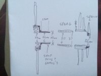
Quick sketch from my bed

The whole thing really hinges on what is the internal diameter of a fixed 11 tooth sprocket.

look up my thread on stripping a DNP Epoch freewheel.

If the smallest internal diameter of the carrier was enough, you maybe able to use the splined carrier from one of them as the sprocket carrier,
Thread on the end is M30x1.0 . Dies available on fleabay for about $20 USD. so you could make a carrier, using the machined down DNP carrier, plus a spacer block.

Or just make your own, stepped if necessary for an 11 tooth, with ID to slip over the 37mm OD sprag needle bearing.

image.jpg
 
Yes, I had been looking at those, but not sure of their internal bore.

The other option is the split style hubs where the freewheel pawls are on the sprocket carrier and the ramps are on the hub.
Would be a matter of cutting the hub down, and machining it to fit in a recess in a new side cover

odyssey-v3-cassette-hub-removable-cogs-56542.jpg
 
NeilP said:
I'd avoid ANY welding, use DP 420 if you have to,
And clamping torque plates/clamps, if they are fixed, going to cause problems

What kind of problems?


You are going to have to source or make your own new side cover for the sporocket.....
That's probably not a problem; I'll do what I did with a 9C front: reuse the threaded side of an old regular hub, and bolt it's flange to the sidecover. Freewheel threads onto that. :)

So the limiting size of my axle would be the center of the old hub's core.


have you heard of 'sprag bearings'

http://simplybearings.co.uk/shop/Bearings-.-Needle+Roller+Clutches/c3_4474_4508/p12408/Branded+HF3020+Needle+Roller+Clutch+Type+One+Way+Bearing+30x37x20mm/product_info.html

One of those, with a 25mm internal diameter bearing

http://simplybearings.co.uk/shop/p1072/Major+Branded+618052RSR+Rubber+Sealed+Thin+Section+Deep+Groove+Ball+Bearing+25x37x7mm/product_info.html
Might be a possibility, but if I can use the existing bearings I'd rather do that, assuming that the hole in the freewheel/hub section is no bigger than that anyway. The only sprag bearings I already have here are far too small a diameter (off an old exercise machine).


Bearings with a bolt in freewheel clutch
Since the limiting factor to the diameter of any axle is the sprocket and freewheel mech, you have an opertunity here to beat that limitation, by making your own side cover with fixed sprocket sprag bearing carrier unit.
Yeah, the catch is as usual money. I'm not sure I can afford all the stuff needed to do it, or that it would all be worth it once I was done, anyway. :) (assuming I can even do it without screwing stuff up and having to redo it more than once, which could greatly increase it's cost).

Still, that's why I'm investigating, and asking. :) I may find it's far cheaper and easier than I thought it would be.

(at the moment it seems like an incredibly complex undertaking as I start mentally cataloguing all the steps)


Confused by two statements you make. You say you won't be able to press an axle in, but then you talk of making your own hydraulic press ?
To press the existing axle out--that ougth to be easy enough. But to press *in* the new axle, alignment has to be better, right? I'm not sure I can guarantee that. I'd rather not screw it up and damage the stator, cuz that's a part I probably can't fix.

I've never made or used a press before, though I've seen the harbor freight ones that basically use a car jack and some I-beams. I don't have I-beams, but I have square tubing, round tubing and thick piping, and a welder, and I can probably make somethign reinforced well enough to take the loads. If not, it should be an interesting failure, at least. :lol: My car jack is also different than theirs--they use a bottle jack and mine is the lever style. (which may be a bottle jack as it's basic core, but I'm not sure it can come apart in a way that allows it to be reassembled to it's original design).


I'd also have to figure out splines or knurling that I could do manually on my little 80-year-old SouthBend lathe that while it works for basic stuff, I don't think I have all the parts for (and I am still learnign how to use it). I am pretty sure I can use the threading/gearmaking part (whcih I have part of) to force the tool holder to traverse a keyway into the center of the axle, whether hollow or solid, while the axle is just clamped to the bed and non-rotating. .

Cost is a really big factor, too, so I can't go out and buy new tools for the job.


With bigger diameters, you can avoid a hollow axle,and make two piece like I did.
I'm gonna have to get the motor apart again and all my bits together, and start measuring things to see what I can actually do with what I have here. It seems like the hollow axle would be easier to make and deal with, especially with the limited tools and primitive skills I have available. :oops:

But I could be wrong, as I don't have a machinist mindset yet, and am unsure of processes and orders of actions to do any of this so far.


If you have to make one new side cover, what the hell, make two, one for the other side too, then you can make the central bearing boss bigger there too for bigger bearing
If I have to use bigger bearing holes in teh covers, I'd just machine them into the existing covers. There *appears* to be enough meat to them to do that, for antying that would fit thru the existing hole in the stator anyway.


Making new sidecovers might be possible, but they'd have to be made out of whatever plate steel I have around here, most of which is not that thick. I would liekly have to bolt or weld layers together to make the different sections of it (bolt-flange to attach to rotor would be a ring, then another ring overlapping that that goes down to the bearign area, then either weld that to a large-diameter pipe section, or a set of flat plate-rings that would bolt or weld together to be thck enough to support bearings/etc.).


My lathe bed isnt' very deep, not enough I think to do the covers, so either I'd have to build somethign to extend that by putting the spindle up higher. Then the chuck isn't all that big, either, so to do larger diameter stuff I'd have to start from the center pieces and build up from there, so the chuck has something to hold onto to ensure it's all centered and circular relative to each other's centers.

Or just manually cut and file all the cover rings/discs/etc. Definitley not looking forward to that much hand-work (my hands don't always work well enough for it, so ti can take a long long time).
 
Another possibility is simply to use a fixed sprocket of whatever size is needed on the wheel itself, and run the chain from that to a jackshaft (probably made from a regular rear hub) that fixes the gearing ratio for me, and has the freewheel, and passes a second chain up to the actual pedals.

Only potential issue for that is all the extra complications it may add to the bike itself.

Might make it easier to eliminate chain alignment problems, though.
 
I started this reply with lots of indented quotes..but it got messy..


Welded torque arms..well, a pain if you have to remove them to strip the motor again, or if they start cracking while out on a ride. With bolt on clamp styles, you can just grab and allen key and tighten them up if they start slopping a bit. Leave a gap between the two halves like I did, and you have plenty of scope without the risk of weld cracking.

That 30 x 37 x 20mm spray roller clutch bearing is not massively expensive, So if you can find ANY old freewheel, strip it down and take a look at the carrier that holds the sprockets.

So you could then use your idea of using the original side cover, and make a fitting for the spray bearing, so slip over. The spray bearing would act as your freewheel..you will still need the main bearing on he inside of the cover. But if y have enough space to machine that out to takee a bigger bearing that is great. That is why I did too I seem to remember....thingks...oh no..what I did was use a bearing with the same OD, but thinner, a 5mm bearing instead of 10 mm wide. That made the ID bigger.

So yes, use the original cover, with bigger internal bearing..you could do that both side covers

Turn down a Top hat shaped piece to bolt on/weld on to your original side cover.

The diameter of the sticking out tube would take the sprag bearing I listed, over the top,
you would then turn down another collar to go over the spray bearing, this collar would have ID to slip over (interference fit) the sprag bearing.
The OD of the collar made to fit inside the cut down to size splined carrier from a standard stripped down freewheel that you have cut down to fit how ever many gears you want. Maybe make that interference fit with a drilling for a pining or even DP420 afterwards.


I see your thoughts on the pressing now...but with careful setup there should be no issue, in fact if you are custom making the press, you can probably make it to do a better job than a traditional press. You can build your press with guides etc to keep it all square.

Thinking of the axle down a sliding fit tube, that is part of the press.
 
NeilP said:
Welded torque arms..well, a pain if you have to remove them to strip the motor again, or if they start cracking while out on a ride. With bolt on clamp styles, you can just grab and allen key and tighten them up if they start slopping a bit. Leave a gap between the two halves like I did, and you have plenty of scope without the risk of weld cracking.
I suppose so. Well, we'll see what turns out to be easier to build. I may well do both. :)


That 30 x 37 x 20mm spray roller clutch bearing is not massively expensive, So if you can find ANY old freewheel, strip it down and take a look at the carrier that holds the sprockets.
Even a little money is usually money I don't have, so since I don't actually *need* to do this project to keep my transportation rolling, I'm avoiding any expenditure I can.

And since it is almost certainly going to be a single speed freewheel on there, just like my previous mod of front-hub-to-rear, it shouldn't need much in the way of support over the axle, beyond simply having the sprocket-side flange bolted to the side cover.

(CrazyBike2's design doesn't lend itself to setting up or fixing a wheel with a derailer on it's chain back there--it's already a PITA to get a wheel in or out, so the simpler I can make that process, the better off I am. If it requires a workstand just to get to the wheel to take it off to change a tire or tube on the road (in case it's something not patchable, which has happened before), I'd be screwed if I was more than a mile or so from home--I simply couldn't walk teh bike back home as I am now.)


I have lots of old multispeed freewheels of various types. I even have a couple of cassette types, which would be more my preference for using on this if I were to do multispeed, vs thread-on. I'm sure if I need to make a multispeed setup on the hub itself I could figure out somethign based on the ideas you've given...but I think that for my purposes it might actually be simpler to have the derailer and sprockets on a separate jackshaft forward of teh wheel itself. :) (remember this is a pretty long bike with plenty of space for that sort of thing)


So you could then use your idea of using the original side cover, and make a fitting for the spray bearing, so slip over. The spray bearing would act as your freewheel..you will still need the main bearing on he inside of the cover. But if y have enough space to machine that out to takee a bigger bearing that is great. That is why I did too I seem to remember....thingks...oh no..what I did was use a bearing with the same OD, but thinner, a 5mm bearing instead of 10 mm wide. That made the ID bigger.
Depending on the space inside the freewheel threads / sprocket-side flange, I may well use a larger ID bearing. But it is much more likely I will use just the existing ones, because of money, and use whatever the largest diameter pipe I have that will still fit in there (lathed for as perfect a fit as I can get to the inner race) for the axle itself. For strength I might put a second pipe inside the first, if I have somethign close enough OD to the others ID to get them to fit tightly, perhaps with a little lathing.


Isee your thoughts on the pressing now...but with careful setup there should be no issue, in fact if you are custom making the press, you can probably make it to do a better job than a traditional press. You can build your press with guides etc to keep it all square.

Thinking of the axle down a sliding fit tube, that is part of the press.
[/quote]
Ah, I think I can picture that, and perhaps it would be just as easy to press in as out, if I make it right. :)


But if anyone remembers that African steel airplane experiment video, well, my results tend to be more like that than a Boeing test flight. :lol: So, we'll see what actually happens. ;)
 
I am fixated at the moment at getting a single or three speed freewheel with an 11 tooth smallest sprocket, it had to be 5 speed....Well it could have been less, but the width wold not have been any less, due to the thickness of the freewheel ratchet mech.

I was thinking that it may be possible with the sprag bearing to make a single speed 11 tooth unit, but ..now I have been measuring up, probably not. the width of those bearings is too great. I'd need a 5mm or 10 mmm max width sprag clutch bearing to do that.
 
Back
Top