Combine volt amp and Ah meter for USD $15

I might put one on the race bike, with the thermocouple located at the outlet of the motor. If my Evo starts getting above 70'C, I will probably have issues. Still, 30-100'C would be more useful.
 
received the amp/volt meter today. really happy. nice packing, nice english manual, really high quality soldering - great stuff, and super cheap!
connected it to the charger, and battery. BAMMM. fet exploded. nice :(

exploded_fet.JPG


any idea what could have gone wrong? there are only 4 cables to be connected. GND and PHASE, battery and charger. that's it :(
will try to replace the fet if i can identify it, and try again. we'll see how the seller reacts. it's not about $25 wasted, but i hate to wait 3-6weeks to get replacement.
 
this seems to be a TIP122. http://datasheet.seekic.com/PdfFile/TIP/STMicroelectronics_TIP122101883.pdf
do you think that this can be directly replaced by a irf4110? i know gate voltage is different, but i'm no electric engineer by any means :)

edit: forget that: they are <$1 even at my local electronic shop. so no need for doing experiments. but the question remains: WHY?
i connected battery (70v) to the output first. but did read that this must not be done.
 
The TIP122 is rated for 100V, so should have been OK for 70V.
Either the part was defective or there may be a short on the board. I would suggest replacing it and try feeding the unit with a lower voltage from a current limited source and see if it lights up OK.
 
fechter said:
The TIP122 is rated for 100V, so should have been OK for 70V.
Either the part was defective or there may be a short on the board. I would suggest replacing it and try feeding the unit with a lower voltage from a current limited source and see if it lights up OK.
that's what i planned to do. buy 2 fets, replace the defective part, check for shorts, and then ramp up voltage from zero until something happens.
that's crazy. this meter looks REALLY good. really high quality. but Q/C seems to suck everywhere.
 
i just replace the fet, and also realized that a diode was desoldered when the short happened. must have been some serious current. i resoldered the diode, but the display remains dead. i guess it's not worth investing more time. maybe someone has another hint what to do, but if not i will see to get a replacement. unfortunately the ebay seller plays dead man.
 
seller replied. excused for not reacting. no problem for me as long as they answer :)
he suggested replacing it, and i pay p&p. 10$. hmmm
we ended up, me buying another one for $24, getting one for free. i'm ok with that. they only sell those amp/voltmeters, and he told me he's gonna test the new ones personally. don't know if he'll do, but i think sometimes bad things can happen and it's noones fault.
 
SamTexas said:
So instead of owning a bad one, you could possibly end up with 3 bad ones for the price of 2. Hmm...
They got about 99.8% good rates. With over 10k sold. So I guess risk is quite low to receive all bad ones. And as I said if seen a lot China crap. This is one of the nicest products I've seen.
 
received two new units. tested the first with 12v. everything fine. connected input to the charger, output to the battery. BAM. seems that the device can't be fed with 90v input. it says:

meter.JPG


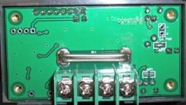
so 40v max for internal supply. ok. got it. but it doesn't say what to do if i want to use 90v and 20a as intended. there is an external supply pad it you remove the back plane. and a solder bridge. but the manual doesn't even cover this.

do i have to open the solder bridge, supply 12v to the external supply pads, and THEN connect 90v to the meter?

please help, as kevin (the seller) keeps saying sorry for replying that late all the time, but isn't really helpful in giving information about installation. and i don't want to blow the second meter left.
 
It looks to me like 40 volts is the real limit on that thing. JMHO.
otherDoc
 
izeman said:
anyone? any help? thanks!
The fourth picture in the ebay listing clearly shows 2 points labeled "Ext PWR" along with the "+" and "-" signs. So that would be where you make the connection. Obviously the external power should be ON before making the other higher voltage connection. Too simple? May be I don't understand your question/problem.

BTW, I don't have this meter so the above is what I WOULD do, not something that I have already done.
 
docnjoj said:
It looks to me like 40 volts is the real limit on that thing. JMHO.
otherDoc
can't be. 40v must be the external supply voltage limit. that's what you use when you want to measure voltages between 0-120V. internal refers to the voltage supply on the INPUT terminals. jmho. that's what i suspect NOW. NOW, that i burnt two of them. kevin will send two new board free of charge, but i'd prefer CLEAR installation instructions. if you look at the ebay description it shows only two pictures. both have full voltage connected to the input and output terminals. external power supply solder pads (for which you have to open device) are not even mentioned. not on ebay, not in the included manual.
but after thinking about it over and over i think that you have to open the solder bridge to disconnect the high voltage from the logic board, and then you can measure the high voltage connected at the input/output terminals. sounds reasonable?
http://cgi.ebay.com/ws/eBayISAPI.dll?ViewItem&item=180869184379
i will never understand why chinese product can't have a well written and correct manual ???
 
SamTexas said:
izeman said:
anyone? any help? thanks!
The fourth picture in the ebay listing clearly shows 2 points labeled "Ext PWR" along with the "+" and "-" signs. So that would be where you make the connection. Obviously the external power should be ON before making the other higher voltage connection. Too simple? May be I don't understand your question/problem.

BTW, I don't have this meter so the above is what I WOULD do, not something that I have already done.
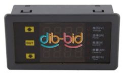
i think you are right. one import thing to do as well is open the solder bridge. because if you don't do that, full input/output voltage will be supplied to the logic board.
 
Hi Guys,

I've bought myself one of this type dual-display-voltage-voltmeter.jpg

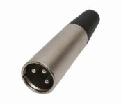
I'm wanting to hook it up in line somehow to check on the battery & charger while charging for a clear display of what's going on. I've got a 3pin male XLR on the charger(see Ping 36V charger)
3_pin_male_xlr_a3m_connector.jpg View attachment 4
Pin 1 is hot

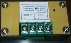
I need to know how to go about wiring the display into the set up. Which wires go onto which terminals on the rear of the dual display unit and then how to connect up to the charger?

Unit rear terminals Voltmeter%201.jpg & Voltmeter%202.jpg


I can't get into the internals of the charger as it's sealed in with some sort of white gap sealant stuff, so I suppose I'll need to hook it up to the charger output XLR or the battery female XLR input on the bike? Anybody have any ideas to help me out with the correct wiring of this? I apreciate any help as I'm not an electrician but I'm ok with following clear logical instructions. Thanks in advance

Regards
Hiconic
 
ian.mich said:
NeilP said:
yeah, but DIY is what this forum is all about lol. Not dissing the CA but its not as cool as finding something yourself and saving some cash too
I sooo love that! There is nothing like using a bit of intuition and some resourcefulness combined with some mechanical aptitude to do something better than you could buy for hopefully a much cheaper price.

why pay someone to do what you coud do yourself?

In saying that I would and will buy a CA as it looks like a value thing. I have a turnigy power meter on my other bike but the first downpour it gets in it wil be fried. The battery is in the same boat because I haven't waterproofed it yet.
 
One alteration to my photo, I used someone elses photo then saw that the diagram on the back of mine was different so here's what mine says, Voltmeter%201.jpg It's the same model VAM No 9020 just different diagram
 
fechter said:
He also lists some that are 'programmable' for under and over voltage, current, capacity, etc. that can trigger an alarm or shutoff when the limit is exceeded.

Just a heads up. Some of the ones with the relay output on the board the relay does not exist. The menu to program it is not there. All that can be programmed is the calibration and Ah of battery.
 
Hi guys,

I'm not sure if I've posted in the right place, have I done the wrong thing in jumping in on this thread ?

I wasn't sure if I needed to start a new thread with my request. I was thinking that this being the same display unit that I was just extending the discussion of the uses for them, I thought that people in this thread would be able to help me out with my request. Do I need to repost with a new thread/topic to get a response? Sorry if I've stepped on anyones toes in doing this, just another dumb-arse noob! :shock:

Regards
Hiconic
 
Izeman, did you remove the jumper and supply the brains from a different source with success? A few pages back somebody else ran one from 12v and measured 100v.

It looks like you ordered the one that both watch's the battery charge and then gives a countdown as it discharges. I only just noticed these one's exist. It would be nice to hear how you get on
 
friendly1uk said:
Izeman, did you remove the jumper and supply the brains from a different source with success? A few pages back somebody else ran one from 12v and measured 100v.

It looks like you ordered the one that both watch's the battery charge and then gives a countdown as it discharges. I only just noticed these one's exist. It would be nice to hear how you get on
who really knows how many variants of that meter exists, and which one has which limits??
i bought a meter that says it can do 90v. it didn't say anything about the external power supply. but a i blew two of them by directly feeding it with 90v i thought something must be wrong ;). my other meter that looks a bit different can handle 90v directly.
i now opened the solder bridge, fed 12v from the charger internally to it, and now it measures 90v just fine. no idea why this isn't explained in the manual.
btw: i can fully recommend both: the seller and the meter. it's just the manual that is misleading (to me??)
 
Back
Top