Cycle Analyst V3 preview and first beta release

Kepler said:
However for the thermistor I was looking to use the S- wire and ground from the hall sensors. This way I just need to feed one wire through the axle.
I don't understand what the S- is used for as its directly connected to ground anyway and seems to me that any ground would do the trick. With this in mind I was thinking I just bridge S- to ground at the CA.

Hopefully this will work and keep my wiring from the controller to the CA at a minimum. Please let me know if there is a problem with wiring this way.
With apologies to George Orwell: "All Gnds are equal, but some Gnds are more equal than others".

The problem is twofold: sensitivity of the electronics to very small voltages and voltages appearing end-to-end in wiring due to (unwanted) currents.

Justin discussed possible issues with sharing thermistor grounds in this post.

The same issue is at work with the shunt. For a 1mOhm shunt, each 0.001v across S-,S+ is interpreted as 1 Amp of shunt current. Normally, there is essentially no current flow in the S+,S- wiring so the voltage at the shunt end is reasonably what appears at the CA PCB pads. However, by sharing a single wire for the shunt signal and CA supply voltage, a voltage will be developed end-to-end on the CA supply (shunt) wiring giving the appearance of shunt current. Although this can be mitigated by zeroing the shunt reading in Setup, noise and normal changes in the CA power utilization will appear as changes to the shunt current. In the worst case, plugging a 1A phone charger into the Aux power jack could easily result in an apparent shunt current change of 100A.

So, what you propose will work from a 30,000ft view, but the fact that all the Gnds are not actually equal can cause problems for CA monitoring features.

  • EDIT - Please see Justin's post below that outlines techniques for minimizing these effects to make this wiring scheme work acceptably.
 
Folks-
A few days back Justin updated the Prelim2-B22 firmware with some additional fixes and produced Prelim3-B22. Both his original Prelim post, the Prelim2 post, as well as the Grin Tech site have this newest version.

Early downloaders of B22 may want to get this latest version. It can be distinguished from Prelim2 by little up/down-arrows adjacent to the 'Poles' and 'Direction' P and D glyphs on the Speedometer and PAS Setup live data preview screens. This version also should eliminate the little jerk in the motor on trip reset.

PasPreviewScreen4.png
 
Kepler said:
I don't understand what the S- is used for as its directly connected to ground anyway and seems to me that any ground would do the trick. With this in mind I was thinking I just bridge S- to ground at the CA.
Please let me know if there is a problem with wiring this way.

Hey Kepler, Teklektic did a great job explaining the downsides to this. But in practice you might be able to make it work good enough IF the following conditions hold true:
a) You don't have any lights/devices powered from the CA's DC power tap,
b) Any accessories plugged into the CA (such as a throttle or PAS) draw a steady and continuous current. So if the throttle draws say 4.5mA, it does 4.5mA when the throttle is off as well as when it turned full tilt.

Even with that, you will find that the offset does drift around with changing wire temperatures so you will need to rezero more frequently, but it shouldn't be too bad (like +- a few 100 mA).

If a single cable is important though, it's pretty easy to find a 7 conductor cable with the same nominal OD and rewire it with that. -Justin
 
hjns said:
Now, I have just flashed to B22, and I like it very much. I also like the way I can enter the rdshunt value in 2 digits before the decimal. Thanks, Justin, for implementing that one as well, so I can now enter 13.75 mOhm in low range and then switch to high range and have the correct rdshunt value of 1.375 mOhm, and still make use of a current limit of more than 99A.

OK, it is clamped though to either 20.00 mOhm in low range, and 2.000 mOhm in high range.

I am really looking forwards to try a limit of 150A at 20S...... although it is difficult enough to get into the 8kW range (99A). I only really achieved that when accelerating from standstill up a 30% hill.....

I bet. At 8kW you'd get your ass accelerated to a lower power region pretty quick unless climbing a wall. That said, if you are running 150A battery currents, it might make sense to have a lower resistance sensing shunt. 150A through 1.4 mOhm is a good 30 watts of heat and I don't imagine your shunt would like that for too long.

Another feature request: Could we perhaps have the capability to flash the CA with a text file with preset variable values in it?

The current .hex file and uploader actually supports this already, but it's not yet organized in a simple 'user editable' fashion because the function and memory locations of all the different parameters haven't been finalized. So the variable preset settings for the B21 firmware are not the same as B22 etc. For sure once it's out of Beta then we will make a revised uploader software that lets you pre-choose all of the parameter options so that you don't have to keep doing button presses after each reflash or upgrade. I agree that currently it's a bit of a pain! -Justin
 
Hey MrBill and thanks for the long summary.

mrbill said:
For some reason when I watched the diagnostic screen, it would always lock in a little over 3 seconds. Maybe my finger isn't steady unless I'm paying attention.

I think that must be the case. I did most of my testing with a twist throttle rather than a thumb throttle, and found even at 0.05V I could get it reliably to lock. I've been thinking about ways to have a little 'count down' timer as you hold the throttle so that you'd be able to know where it's at.

I can see myself using power throttle with a lower maximum limit when I'm riding with non-ebikers, perhaps using an alternate preset.

It was nice to up-shift to a taller gear and have the controller instantly ramp back the throttle to maintain the set power. And, it was also nice when reaching the top of a rise to have the motor continue to apply constant power as the RPMs increased. On the other hand, I miss the "press me back into my seat"--I ride a recumbent--feel that occurs with a voltage-based cruise control when the road heads up.

Yeah, that well describes the experience of different throttle control strategies. For auto-cruise control, I would think that the pass-thru throttle would generally be the most appropriate since the idea is usually to preserve your speed. And then if you want variable power levels for the sake of stretching the battery life or riding along pedal bikes, then set the Aux Input to control your power limit with a switch or potentiometer.

Throttle up-ramp and fast up-ramp seems to work only in "Speed" and "Power" throttle modes. (I assume it also works in "Current" throttle, although I didn't test this, figuring the behavior was almost the same as "Power" throttle as I use LiFe batteries that have good regulation.)

The output ramps apply equally the same regardless of your input throttle mode. So I think that you are confusing delays associated with the speed and power feedback loops (IntSGain, WGain resepectively) with the actual throttle ramp limiting. It's a little complicated with so many different parameters all having their affect on the throttle output, but the throttle output ramps are applied across the board to the output signal, and nothing can over-ride that and make it change faster (except the ebrake, which causes an abrupt drop to 0V).

In general it seems that the cruise control has trouble locking when the actual "Speed" or "Power" is varying significantly, even if the throttle voltage is being held within a tight range for the required lock time.

That's interesting and it must be that the variations in power of the ebike are causing you to shift your throttle position slightly, just enough to release the cruise latch counter. It sounds like I might want to increase the upper bounds, to like +-0.4V rather than +-0.25V. In theory the whole cruise timing and latch process is completely independent of the throttle mode selected.

In "Pass-Thru" mode the throttle operates without delay as if it's connected to the controller (although subject to the limits, speed, current, power, temperature, etc., set elsewhere). Most of the time I think I prefer this, but it would be nice to have the option of up-ramp, down-ramp, and fast up-ramp available in Pass-Thru mode.

Just to be clear, the throttle ramps equally apply in pass thru throttle mode as well. Can you tell me what values of the throttle ramp in Sec/Volt you were using? You should be able to go to the diagnostic screen and see VOut climb up and down at the same rate as your ramp setting.

The battery capacity icon showed an empty battery when I had 8 Ah (out of 53 Ah) still unused. This would be about 15% State of Charge (SOC). Does this icon behave like most auto fuel gauges that show "Empty" when there's still a few gallons left in the tank?

There is a lot of variation in what people mean to be an 'empty' tank of battery. I have the LiPo curve set so that 0% is at 2.9V / cell, which is where most of the packs we have dealt with have their BMS cutoff. But apparently a lot of people here are calling 3.5V per cell to be totally flat, so they have the opposite situation of the CA's icon showing significant charge left when according to them the pack is flat.

Also, what happened to the numeric percent SOC statistic in Beta22? I liked seeing this in Beta21.

That was just there for diagnostics but is not going to be in the final release. It is a value that is at best +-10% and if shown as a number then it gets taken literally by people. The battery graphic on the first screen is about as meaningful as the SOC value can be represented. Then if you want exactitude, you look at the Ah and be in the habit of resetting the CA at the start of each full charge.

I noticed that the trip PAS screen is missing a couple of stats that would be interesting to see: "Maximum Human Power" and "Maximum Human RPM". Perhaps these could be displayed alternating every few seconds with the Average figure.

Good points! I think max human power would be super fun to have and am surprised I didn't think to fit that in from the getgo. Will try to squeeze out a few more bytes of memory to make this show. That could make up for your lack of brownies on the B21 RShunt issue ;)
 
justin_le said:
The current .hex file and uploader actually supports this already, ...
The pre-1.1 uploader actually can't handle this. I tried downloading a small hex file with only parameters as an overlay to a pre-installed xxx_NoCal.hex file. Unfortunately, the uploader erased everything as a matter of course prior to the actual download resulting in a blank CA except for the parameters..

Does 1.1 pre-erase the same way? If so, an option to suppress the shotgun erasure would open the door to partial parameter-only downloads. Sorry - no means to test since 1.1 doesn't like my machine...
 
Hi Everyone,

First off i would like to thank Justin for making the Cycle Analyst and providing great support for it. I currently have a Magic Pie 3 setup, with a 48v 10Ah battery and have been using the analyst for a week or so, so please forgive me if some of my questions may be wrong or stupid :)

My issue is with the Regen indication. I connected the Analyst to the Throttle signal as it was described, so my throttle is going through the analyst before going to the controller. Additionally i connected the brake leavers in parallel to the Magic Pie signals.

I upgraded to the 22 beta version a day or so ago and everything seems to be working fine. However, i did do a calibration reset (in the Shunt Calibration menu) and now my power consumption is showing 0W in idle, when it was at 2 - 3 when i had version 21, although i must admit i didn't do a calibration reset then.

The first issue i have is that almost every 5 - 10 seconds the consumption in idle goes to -0W. If i go to the Regen menu and monitor the regen % then it actually increases while in idle by it self every 5 - 10 seconds. Is this because i configured my analyst wrong in some way or is this a bug?

Additionally, i have been using my bike for 2 weeks now. Even with the 21 version on the analyst, when i press the brakes, although the Magic Pie is braking for 5 - 15 seconds on a mild hill, i only see the regen for a moment (like a second or two) going to -200w or somewhere there, and after that, although the Magic Pie is still braking, the regen and power consumption drops to 0W and stays there until i begin going again.

I talked to the people who built the controller on Magic pie and here is the reply:

Our engineer said we have regen brake function but you can’t get the accurate data from Cycle Analyst.
We have that function but it would be difficult for our customer test it without professional tools.

The Regen braking recharging function will become very clear when you climb down the hills.You can add one Clamp current meter between the battery power cable and motor ,Once you climb down the hills and brake suddenly ,you will see current flow into the battery obviously.


So what is the deal here? :) Is this a bug of some sort or its just how it is? Perhaps while the newer version is being worked on, someone could look into it?

Any sort of reply would be appreciated on the matter. Tnx in advance.
 
fgcity said:
The first issue i have is that almost every 5 - 10 seconds the consumption in idle goes to -0W. If i go to the Regen menu and monitor the regen % then it actually increases while in idle by it self every 5 - 10 seconds. Is this because i configured my analyst wrong in some way or is this a bug?

This is really insignificant and is the result of small amounts of electrical noise on the shunt sense leads. Once you have even the tiniest usage of actual Amp-Hours on the bike then the little blips of -0W will have no effect on the purported %regen.

Additionally, i have been using my bike for 2 weeks now. Even with the 21 version on the analyst, when i press the brakes, although the Magic Pie is braking for 5 - 15 seconds on a mild hill, i only see the regen for a moment (like a second or two) going to -200w or somewhere there, and after that, although the Magic Pie is still braking, the regen and power consumption drops to 0W and stays there until i begin going again.

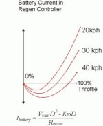
Almost for sure what this means is that the motor is going into a full regen where it is basically shorting out all the mosfets and indeed nothing goes back to the battery in that case. With regenerative braking, as the braking force increases your regen amps initially increases, then it levels off, and then as you do regen to the maximum the regen current back into the pack falls back to zero again, even though the current through the windings is at a maximum.

Regen Amps.jpg

The regen amps is where the graph goes negative, and if the the duty cycle 'D' is shown from 0-100%. At the 0% duty, you have shorted out all the motor windings together, which results in a very large braking force from the motor, but no current back into a battery since it is all dissipated as heat in the windings.

I talked to the people who built the controller on Magic pie and here is the reply:
Our engineer said we have regen brake function but you can’t get the accurate data from Cycle Analyst.

So what is the deal here? :)

The deal here is that you probably have some translation/communication issues but the overal sentiment expressed by the engineer is wrong. The CA sees exactly the current flowing in or out of the battery pack, and if it shows 0A then that means there is no current flowing into the battery. -Justin
 
Do you think this is something that can be fixed with a simple firmware update by Golden Motors?
 
justin_le said:
mrbill said:
For some reason when I watched the diagnostic screen, it would always lock in a little over 3 seconds. Maybe my finger isn't steady unless I'm paying attention.

I think that must be the case. I did most of my testing with a twist throttle rather than a thumb throttle, and found even at 0.05V I could get it reliably to lock. I've been thinking about ways to have a little 'count down' timer as you hold the throttle so that you'd be able to know where it's at.

In general it seems that the cruise control has trouble locking when the actual "Speed" or "Power" is varying significantly, even if the throttle voltage is being held within a tight range for the required lock time.

That's interesting and it must be that the variations in power of the ebike are causing you to shift your throttle position slightly, just enough to release the cruise latch counter. It sounds like I might want to increase the upper bounds, to like +-0.4V rather than +-0.25V. In theory the whole cruise timing and latch process is completely independent of the throttle mode selected.

The problem may be that it locks within 0.05V no matter the setting of the threshold voltage. Here is a video I took showing the threshold voltage set to 0.25V. Then when I attempt to set the cruise control while purposely varying the input within the 0.25V threshold, the cruise can be seen attempting to lock (as seen by the flashing "In") but then losing lock a second later or when the throttle is released.

[youtube]zLsWxHtUfVg[/youtube]

Is it possible that my throttle variations are causing voltage peaks wider than the threshold voltage that do not show on the CA? I set the Averaging to "3" to see quicker changes on the display in this video.

I can see myself using power throttle with a lower maximum limit when I'm riding with non-ebikers, perhaps using an alternate preset.

It was nice to up-shift to a taller gear and have the controller instantly ramp back the throttle to maintain the set power. And, it was also nice when reaching the top of a rise to have the motor continue to apply constant power as the RPMs increased. On the other hand, I miss the "press me back into my seat"--I ride a recumbent--feel that occurs with a voltage-based cruise control when the road heads up.

Yeah, that well describes the experience of different throttle control strategies. For auto-cruise control, I would think that the pass-thru throttle would generally be the most appropriate since the idea is usually to preserve your speed. And then if you want variable power levels for the sake of stretching the battery life or riding along pedal bikes, then set the Aux Input to control your power limit with a switch or potentiometer.

My idea here is to fix the power at a certain level, say, when riding over terrain of varying grade with other cyclists in close formation without having to make frequent small throttle or cruise adjustments. The power level would be usually somewhere around 250-400 watts (in). The human-powered cyclists generally ride power-limited, so the power-based cruise ought to be able to match their profile better than a voltage throttle over varying terrain. Your idea of using a preset with a lower power limit, e.g. 500 or 600 watts, would make it easier to settle on the correct power level without overshooting. I'll have to test this the next time I go riding with others.

I know that using standard voltage throttle with cruise, I tend to pull away as the grade increases and tend to get caught up to as the grade decreases (if I was climbing the steeper terrain at human-powered speed). So, on varying terrain I have to make continuous adjustments with the throttle or by varying human effort, if I can.

Throttle up-ramp and fast up-ramp seems to work only in "Speed" and "Power" throttle modes. (I assume it also works in "Current" throttle, although I didn't test this, figuring the behavior was almost the same as "Power" throttle as I use LiFe batteries that have good regulation.)

The output ramps apply equally the same regardless of your input throttle mode. So I think that you are confusing delays associated with the speed and power feedback loops (IntSGain, WGain resepectively) with the actual throttle ramp limiting. It's a little complicated with so many different parameters all having their affect on the throttle output, but the throttle output ramps are applied across the board to the output signal, and nothing can over-ride that and make it change faster (except the ebrake, which causes an abrupt drop to 0V).

In "Pass-Thru" mode the throttle operates without delay as if it's connected to the controller (although subject to the limits, speed, current, power, temperature, etc., set elsewhere). Most of the time I think I prefer this, but it would be nice to have the option of up-ramp, down-ramp, and fast up-ramp available in Pass-Thru mode.

Just to be clear, the throttle ramps equally apply in pass thru throttle mode as well. Can you tell me what values of the throttle ramp in Sec/Volt you were using? You should be able to go to the diagnostic screen and see VOut climb up and down at the same rate as your ramp setting.

After putting the bike on the trainer to create an artificial load I confirmed that you are correct. The throttle Out parameters, upRamp and fastRamp, do have an effect in Pass-Thru mode. Perhaps in Power mode the ramp behavior is more obvious because a small throw of the lever generally results in higher power than in Pass-Thru mode. Or, as you suggested, I am really noticing the effect of S or W gain in those modes since these limits are usually binding in their respective throttle modes.

On my ride I used the following settings:

ThrO Pass-Thru
ThrO upRamp - 0.30 sec/Volt
ThrO fastRamp - 0.05 sec/Volt

SLim IntSGain - 100
SLim PSGain - 100V/min
SLim DSGain - 100
PLim AGain - 100
PLim WGain - 50

In the videos I changed Thro upRamp to 1.30 sec/Volt so that I could more easily observe its effect.

I was hoping to be able to find a combination of ThrO upRamp and fastRamp that would maintain good throttle response--not too slow or delayed--but would also reduce drivetrain "slam" when introducing motor power. But I haven't been able to find a combination that doesn't add an irritating delay of the sort one used to see on early-1970s GM carbureted engines that often had an annoying hesitation after pressing the gas pedal.

The video below demonstrates a few instances (starting at about halfway through) of cruising under power and dropping out motor power, only to reintroduce it while the drivetrain is still in motion. The point at which motor power is re-introduced to the system one can briefly see over 20-30 Amps on the CA display--watch carefully or you'll miss it--at the moment one hears the "slam". It's this high peak I'm trying to soften without introducing too much delay in throttle response. Is this achievable?

[youtube]sSdDVr9q6Fc[/youtube]

Can the 2 Amp threshold for fastRamp->upRamp transition be set by the user? I think I'd choose 3 Amps on my system as the full-throttle freespin current on my motor is between 2 and 3 Amps.
 
An update to my prior posting.

I rode again yesterday to check on the two behaviors I highlighted in the videos.

1) With the ThrO -> upRamp set to 1.3 or 1.5 seconds/volt I found that drivetrain "slam" was, in fact, reduced and less severe than with a shorter 0.3 Sec/Volt upRamp time from last Sunday, even though on the trainer it sounded just as loud. When riding the bike I can feel that the "slam" wasn't as strong. I can still sometimes get a little more jerk from the bike if I go zero to full-throttle in a higher gear, but the jerk is weaker than it was with a shorter upRamp time or without this feature. On the whole, I think this is working well.

2) I still think the cruise threshold voltage needs to be re-examined.

I use a thumb throttle, and with a thumb throttle it's less natural to grasp both the moving and stationary parts of the control than it is with a twist throttle. I can do this with a thumb throttle, but it's means pinching across the seam between the moving and non-moving parts and is not a natural way to use a thumb throttle.

Even at 0.25 volts, unless I've gripped the throttle in a manner that guarantees that it doesn't move at all, getting the cruise to lock is hit or miss. Sometimes it takes longer than 3 seconds to lock, sometimes I get the flashing square on the throttle position icon only to have the lock fail when I release the throttle (as in the video above), and sometimes it works as expected.

Maybe the threshold voltage up to 0.25 volts is sufficient, but the detection of voltage swings that violate the threshold could be changed so that it requires a longer violation to reset the throttle cruise lock timer.

In the case when I get the flashing icon (or flashing "In") only to have the lock fail when I release the throttle, is it possible that the lock is being made for a short time, indicated by the flashing icon, but since the control is not being held steady, the cruise lock gets broken immediately by the same rule that one breaks cruise by flipping the throttle briefly from its resting position? Does the software require that when the throttle is used to break cruise it do so only when it is thrown from its resting position?

Question: Is threshold voltage defined as +- 0.25 volts from current throttle setting or +-0.125 volts from current throttle setting?
 
izeman said:
EDIT: WHAT THE F$%$§%$§&%§&&CK!!!! THIS F$%$§%§%§ING PROLIFIC chip. both of the two i had available where prolific. none of them worked. i now tested my home brew rs232>ttl converter on the internal com1 port of my windows desktop pc (i had to dig deep in my hardware trunk to find the com1 cable :) ) - plugged it in and it worked. :) really happy now!
sorry for the bad words, but i just can't believe that i spent almost a WHOLE WEEKEND with this bad adapter for nothing.
this goes out as a word of warning to everyone: BUY THAT CABLE FROM JUSTIN and save yourself trouble.

Glad that you got it sorted. That is really unfortunate though that a lot of people have had issues with 3rd party cables, since the whole intent was to make the CA use an open standard and be compatible with other off the shelf TTL serial adapters. The problem here might be with the proliferation of cheap knock-off "prolific" devices that aren't the legitimate product. Porlific themselves have issues press releases about this problem, and it shows up on other forums too:
http://www.eevblog.com/forum/reviews/note-how-to-not-get-scammed-with-prolific-(pl2303)-usb-serial-adapters/
http://vk1od.net/software/ATB/PL2303.htm

So those $2 ebay cables from china are almost for sure imitation juink, given that the IC itself alone costs about this much. As I mentioned we did most of our early work using cables based on the prolific chip which mostly worked, but found that the FTDI devices had better plug-and-play driver support with windows auto-detecting them as a COM device without driver downloads etc.
 
mrbill said:
Question: Is threshold voltage defined as +- 0.25 volts from current throttle setting or +-0.125 volts from current throttle setting?

It should be +-0.25V, but it's not based so much on the current throttle setting as the last time the throttle setting exceeded one of those bounds, so you could have a case where the throttle band is like +0.05 -0.45 from where you actually are at. I'll admit I haven't tried it with a thumb throttle yet or with the larger bounds to check the performance, so I'll get a thumb throttle put on my own bike this weekend and play around to see if there are behaviors that can be better refined. -Justin
 
justin_le said:
I have the LiPo curve set so that 0% is at 2.9V / cell, which is where most of the packs we have dealt with have their BMS cutoff. But apparently a lot of people here are calling 3.5V per cell to be totally flat, so they have the opposite situation of the CA's icon showing significant charge left when according to them the pack is flat.

I was wondering about that icon - is the CA SOC indicator calculated based off of a curve for lipo, or is the 'curve" linear? If linear, wouldn't a number closer to the lipo cliff (3.5) give a more accurate estimation of SOC? Compared to my charger (PL 8), I noticed the CA shows high and seems a little off compared to the actual AH available.
 
would it be possible for the end user to enter a voltage that they consider flat ?
as you have said, lots of us don't like going lower than 3.5v / cell under load.

Jason
 
givitago said:
I was wondering about that icon - is the CA SOC indicator calculated based off of a curve for lipo, or is the 'curve" linear? If linear, wouldn't a number closer to the lipo cliff (3.5) give a more accurate estimation of SOC? Compared to my charger (PL 8), I noticed the CA shows high and seems a little off compared to the actual AH available.

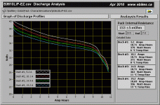
It's a non-linear curve fit, well 16 SOC/voltage reference points with linear interpolation between them. With LiPo there isn't as much of a cliff at 3.5V like there is with other chemistries, and there is quite a bit of usable capacity between the 3.5V/cell and 3.0V/cell. Here is the discharge curve that I used to generate the SOC lookup table for LiPo. It's a nominal 36V 10Ah lipo pack using AEenergy Cells, a pretty significant player in supplying lipo ebike batteries to the OEM market:
B3610LiP-EZ_Graph.gif

You can see that at the 5A discharge rate the pack hits 3.5V/cell at about 6.5Ah, which is way less than the 10.7Ah that it provides before BMS cutoff. Accounting for the internal resistance of the battery the open circuit voltage (which is what the CA uses for the lookup table) looks like it would hit 3.5V at about 8Ah consumed. So at 3.5V there is still a full 25% capacity remaining in the LiPo pack.

I noticed the CA shows high and seems a little off compared to the actual AH available
I've been noticing it seems on the optimistic side too in the real world with the samsung LiMn packs, and will be making some tweaks to the tables to make sure it's properly representative. Ultimately the SOC indicator is relying on your voltage rather than your amp-hour data, with the amp-hours only providing for smooth transition behavior when you are drawing large currents and the voltage data isn't very meaningful. But over time it's always settling on a SOC based on the open circuit voltage (except with LiFe, where in the flat 3.25-3.35 V/cell range it's only going off Ah).

Diamondback said:
would it be possible for the end user to enter a voltage that they consider flat ?
as you have said, lots of us don't like going lower than 3.5v / cell under load.

That's what I'm looking into. The easiest thing would be to have several different look-up tables going to different end points (LiPo2.9, LiPo3.3, LiPo3.5 etc.). Making it so that you can just specify the end of charge voltage that you consider 0% and have the CA deduce the details and rescale table would be nice but is a lot trickier to implement.
 
justin_le said:
Diamondback said:
would it be possible for the end user to enter a voltage that they consider flat ?
as you have said, lots of us don't like going lower than 3.5v / cell under load.

That's what I'm looking into. The easiest thing would be to have several different look-up tables going to different end points (LiPo2.9, LiPo3.3, LiPo3.5 etc.). Making it so that you can just specify the end of charge voltage that you consider 0% and have the CA deduce the details and rescale table would be nice but is a lot trickier to implement.


that would be sweet indeed :D

thanks again for all the time and effort that has gone into the whole CA thing over the years too.

Jason.
 
justin_le said:
It's a non-linear curve fit, well 16 SOC/voltage reference points with linear interpolation between them. With LiPo there isn't as much of a cliff at 3.5V like there is with other chemistries, and there is quite a bit of usable capacity between the 3.5V/cell and 3.0V/cell. Here is the discharge curve that I used to generate the SOC lookup table for LiPo. It's a nominal 36V 10Ah lipo pack using AEenergy Cells, a pretty significant player in supplying lipo ebike batteries to the OEM market:

Justin.

For us guys running high-discharge/low I/R "hobby type" LiPos the discharge curves are flatter and the 'cliff' steeper. As a result, we generally don't run them below 3.6V/cell or so and the SOC estimate will be less accurate.

I do notice that the cruise is cancelling on its own in a somewhat random fashion with my R/C drive setup with pass-thru throttle. I'm not riding it, just spinning the wheel unloaded.

BTW. With regard to the noise problem on the thermistor input, I changed to shielded cable with the shield connected to -ve and this greatly reduced the jitter. It is still not completely stable under part throttle with the CC160 controller. Is there anything else you can recommend to reduce the instability in the temperature reading? Otherwise, V22b is working well.

Cheers,
 
rscamp said:
Justin.

For us guys running high-discharge/low I/R "hobby type" LiPos the discharge curves are flatter and the 'cliff' steeper. As a result, we generally don't run them below 3.6V/cell or so and the SOC estimate will be less accurate.

I do notice that the cruise is cancelling on its own in a somewhat random fashion with my R/C drive setup with pass-thru throttle. I'm not riding it, just spinning the wheel unloaded.

BTW. With regard to the noise problem on the thermistor input, I changed to shielded cable with the shield connected to -ve and this greatly reduced the jitter. It is still not completely stable under part throttle with the CC160 controller. Is there anything else you can recommend to reduce the instability in the temperature reading? Otherwise, V22b is working well.

Cheers,

Further to my last post, here are a few observations and questions resulting from observed behaviour after more experimentation.

I am closing dry relay contacts to short pins 2 & 4 on the Ebrake Cutoff connector to enable ebrake. The screen throttle graphic shows the ebrake enabled graphic. But the throttle output of the R/C controller is not going to zero with ebrake enable. Is the R/C pulse signal from the CA stopped with ebrake? The CC Phoenix HV160 is acting as if it isn't getting the PWM signal from the CA when the ebrake is enabled. For example, after a brake enable cycle, the HV160 is reporting loss of the PWM signal with 5 beeps.

Maybe the HV160 controller is maintaining throttle with loss of signal? Although according to the Phoenix user manual it is supposed to go to zero throttle on loss of signal so this is a bit of a puzzle.

I'm also getting a small shift upward in temperature reading (about 0.2 Deg. C) and the screen of the CA gets slightly brighter with ebrake enable. I have read in other posts that a shift in temperature reading can be the result of small shifts in ground potential in the CA.
 
Printable Setup Summary for CA v3B22-Prelim3 - Now B22

(Note: B22 Prelim3 has been upgraded to B22 - this reflects the final B22 release!)

The setting summary for the newer v3.0 Prelim release is available here.
The setting summary for the previous v3B21 release is available here.
Unofficial User Guide is available here.
Please see the Grin Tech Site for a detailed explanation of Setup Parameters.

Printable versions for saving settings - tabular format for multiple presets (1UP.PDF, 2UP.PDF, XLS):View attachment CA_V3B22P3_ConfigSettings.zip
 
An Unofficial User Guide is posted here. This Guide replaces the set of three PDFs of the earlier Installation Guide and substantially expands the content. Although everything is in a single document, effort has been made to break the sections on page boundaries so it's easy to print sections of interest.


There have been lots of interesting questions since B21 was released and quite a bit of the new content was drawn from their resolution. Thanks to everyone for posting! :D

This guide reflects the state of affairs through B22-Prelim3. As soon as B22 is released an updated guide will be posted to reflect any last minute tweaks. New Config forms are posted above - these are good to record B22P3 settings when moving to B22.

Enjoy!
 
Back
Top